Two years ago I already built a word clock with NeoPixel LEDs. You can find the article about it here. At that time I built the word clock only with an Arduino and queried the time via radio. But this time the plan is to make the clock bigger, prettier and with more features. The word clock with WiFi gets the time from an NTP server and can control some functions via an HTML webserver on the microcontroller (ESP8266). Here is a quick overview of all features before I get into the step-by-step instructions.
Features of the clock:
- has 6 modes (Clock, Digital Clock, SPIRAL animation, TETRIS, SNAKE, PONG)
- receives time updates via a NTP server
- automatic switches between summer and winter time
- provides easy WIFI setup with WifiManager
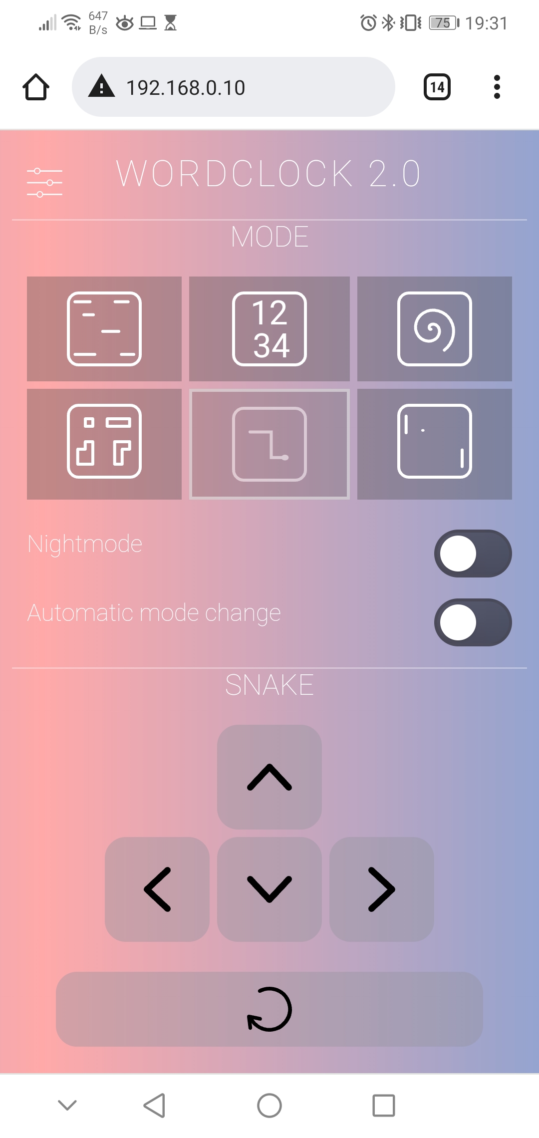
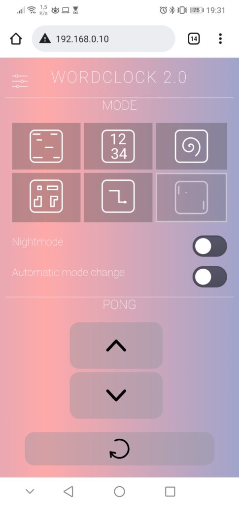
- has a HTML webserver interface for configuration and control
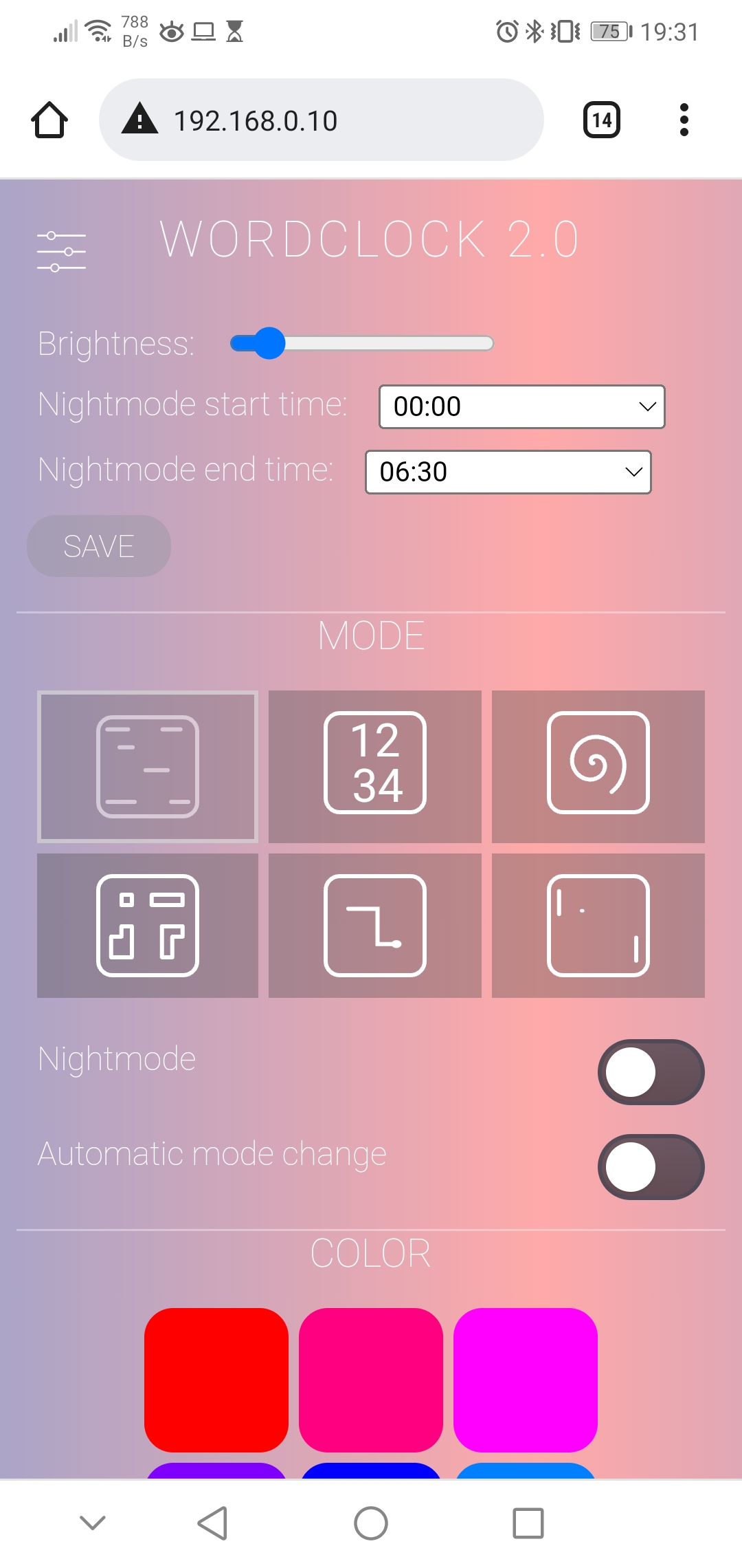
- color of display is configurable
- night mode is configurable (start and end time)
- brightness of LEDs is adjustable
- automatic mode change every 10 seconds (optional)
- has a physical button to change mode or enable night mode without webserver
- an automatic current limiting of LEDs protects the power supply
Languages:
I provide the source code and front plate layout for German, English and Italian. See detailed instructions in the FAQ section below.
Content
- Material for the Word Clock with WiFi
- Step-by-Step Instructions: The Hardware
- 1. STEP: Drawing the front panel foil
- 2. STEP: Sticking the front panel foil on the glass plate
- 3. STEP: Cut and build the light grid
- 4. STEP: Mounting the electronics components
- 5. STEP: Bring everyting together
- Look at the Heart: The Software
1. Material for the Word Clock with WiFi
You need the following material for building this clock:
- wooden picture frame 50x50cm (about 2 cm deep),
- NeoPixel-Strip with 125x WS2812b LEDs (30 LEDs/m) (amazon.de*)
- ESP8266 NodeMCU V3 (amazon.de*),
- USB power supply 5V/3A (amazon.de*),
- cardboard 50x50cm,
- white backing paper,
- 470 Ohm resistor,
- 1000uF capacitor,
- push button (amazon.de*),
- micro USB socket (amazon.de*),
- micro USB cable (amazon.de*),
- some cables
Additionally, some special tools are needed:
- soldering iron
- spray bottle
- hot glue
- cutter knife
* The links are affiliate links. The offers do not come from me, however, I receive a commission through the reference, if then a purchase takes place, but without you incurring additional costs.
2. Step-by-Step Instructions: The Hardware
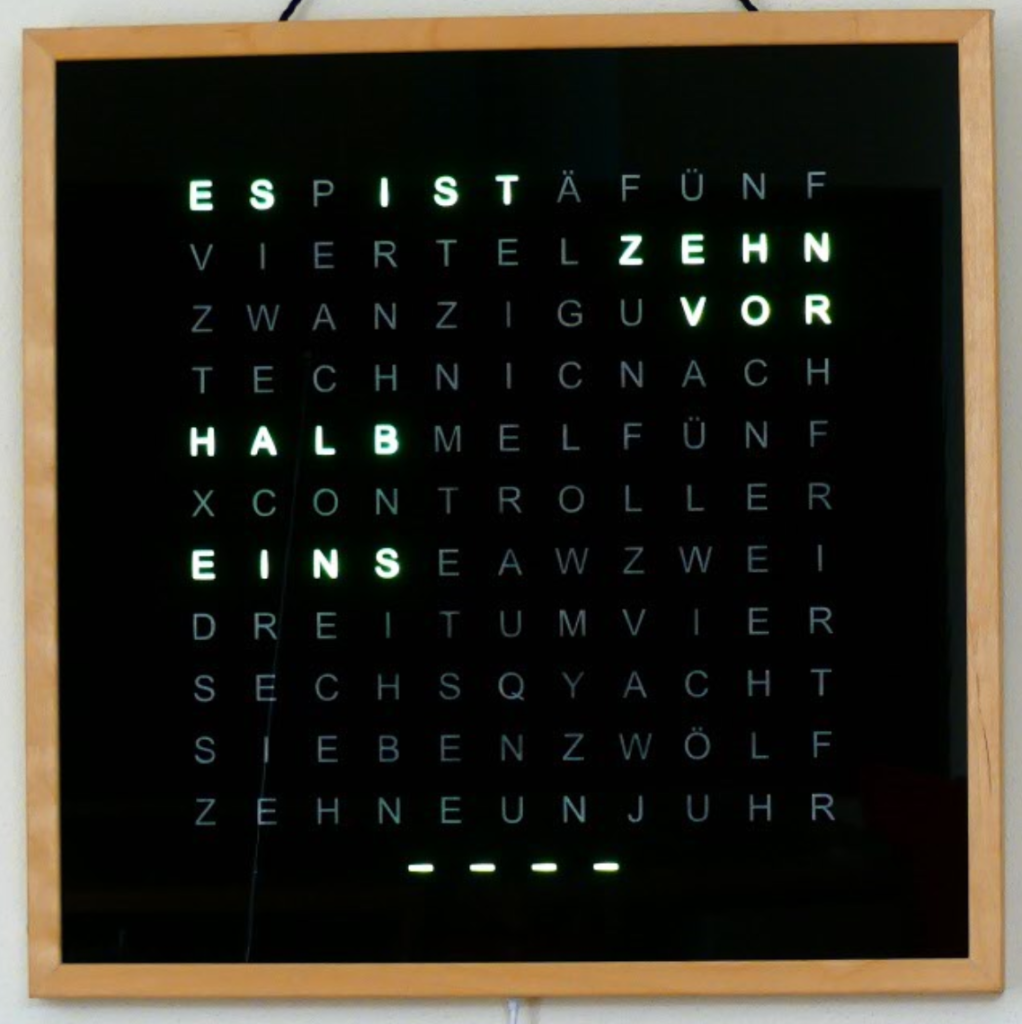
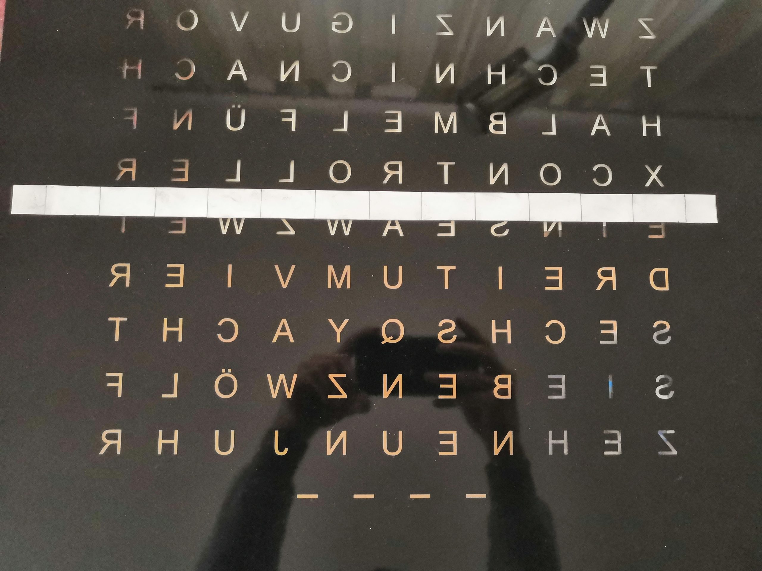
I will describe the build process of the hardware as step-by-step instructions as this will give you the best overview of the project. The mechanical base is again a particularly deep picture frame with a 500×500 mm glass plate. The distinguishing feature of the clock is of course the front panel, which this time contains 121 letters. That means it has eleven lines instead of only ten, which offers several advantages. On the one hand, it allows me to display my name “Techniccontroller”, on the other hand, it allows me to display two letters on top of each other. More details about this topic are in the chapter Digital clock.
STEP 1: Drawing the front panel foil
I decided to have the foil for the front panel lasered instead of cutting out each letter individually from the foil with a knife as I did with the first clock. To laser the foil you need a vector graphic of the foil. This can be done best with the free program Inkscape.
I have created a detailed How-To, in which I show how to draw the front plate with Inkscape:
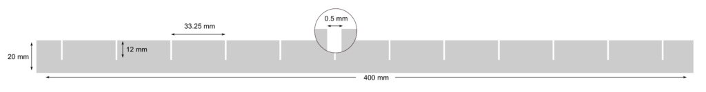
You can also use my Inkscape template: Link to GitHub. The distance between the letters is 33.25 mm in both directions (horizontal and vertical) because I use a LED strip with 30 LEDs per meter.
STEP 2: Sticking the front panel foil on the glass plate
Sticking the foil onto the glass plate is a bit tricky. But with the following tips it worked well for me:
- Clean the work surface thoroughly.
- Clean the glass plate with glass cleaner.
- Spray hands with a water-soap mixture (1L water + 1 spoon of dish soap).
- Remove the protective film from the adhesive foil.
- Wet the glass plate and the foil with the mixture of water and dish soap from a spray bottle.
- Place the glass plate on the foil and using a squeegee with a felt edge, carefully brush all air bubbles from the center to the edge.
- Turn the glass plate over and spray transfer the paper side of the adhesive film with the water-soap mixture.
- Squeegee strongly and evenly from the inside out (5-10 minutes).
- You can remove the transfer paper after a drying time of 10-12 hours. Be careful to remove the paper from the top left to the bottom right at a flat angle so as not to damage the letters E and F.
Detailed instructions for sticking with a few additional pictures can be found here (german):
STEP 3: Cut and build the light grid
The light grid prevents the individual LEDs from shining into other letters. In addition, it serves as a reflector, which ensures uniform illumination of the individual letters. I use a little stronger cardboard, which I cut with scissors. Specifically, I cut 25 strips with the following dimensions:
Then I put the strips together to form a grid structure and paint them with mirror paint. This helps to reflect the light from the LEDs better. Since the grid has bent a lot, I glued wooden rods on two sides to stiffen it.

When gluing the light grid to the back of the picture frame later, you may have to cut a few notches for the cables so that the light grid is flush with the back and prevents light leakage (see pictures below).
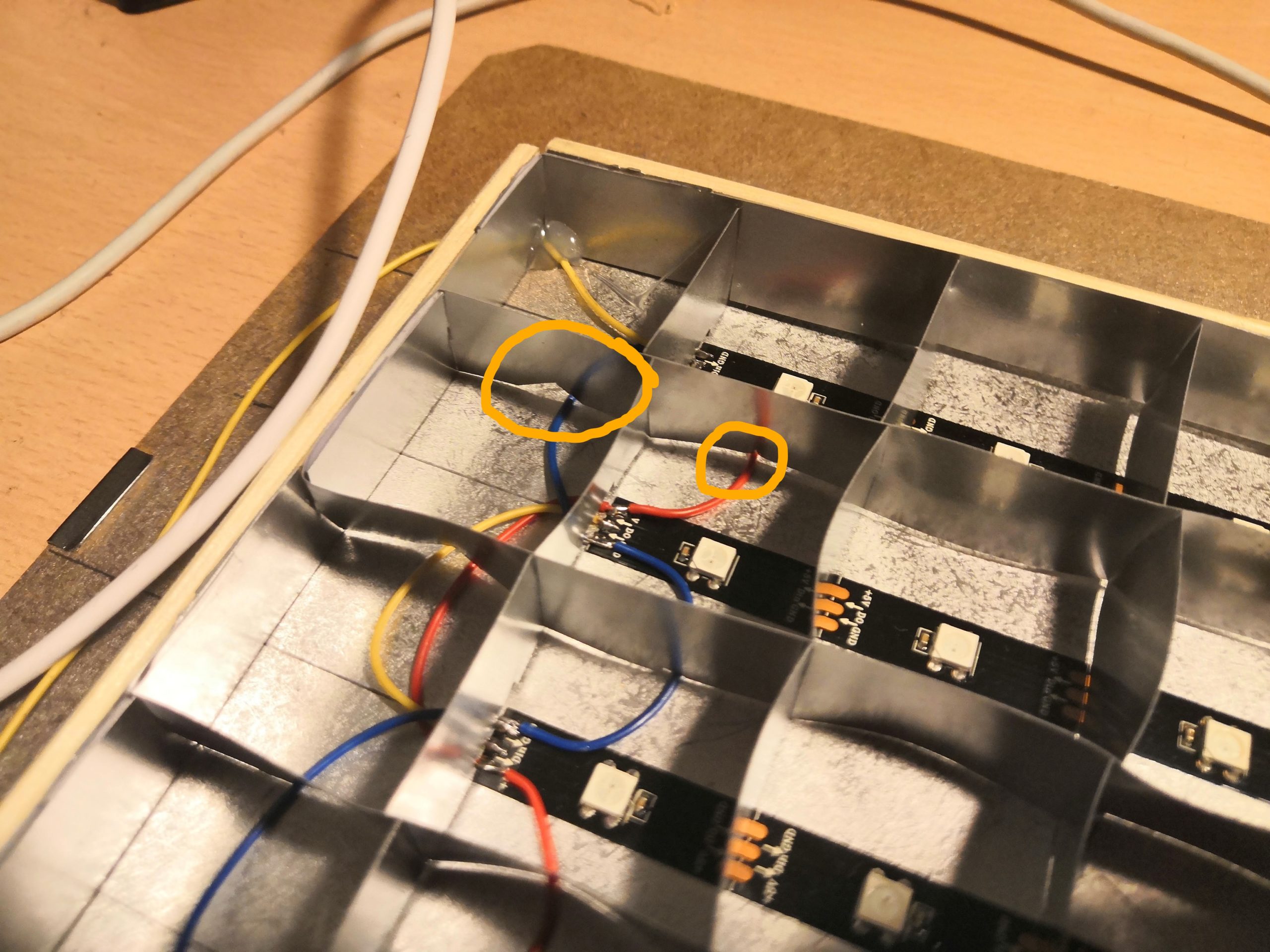
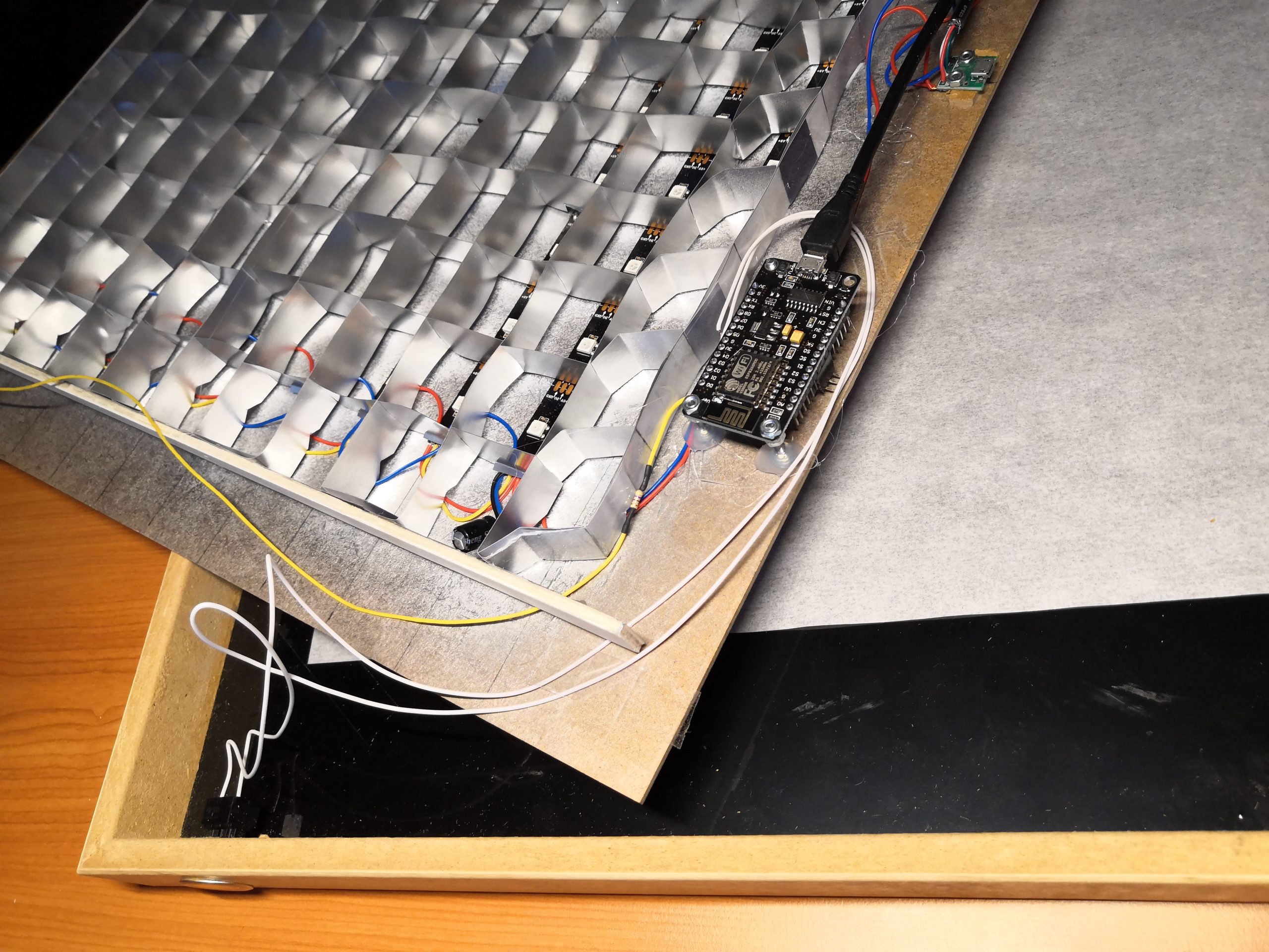
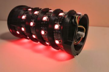
STEP 4: Mounting the electronic components
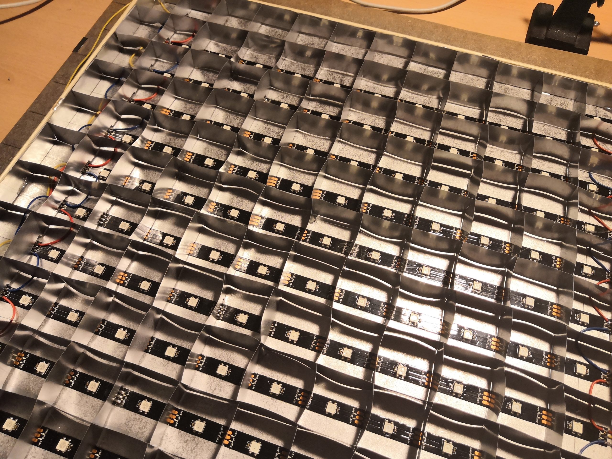
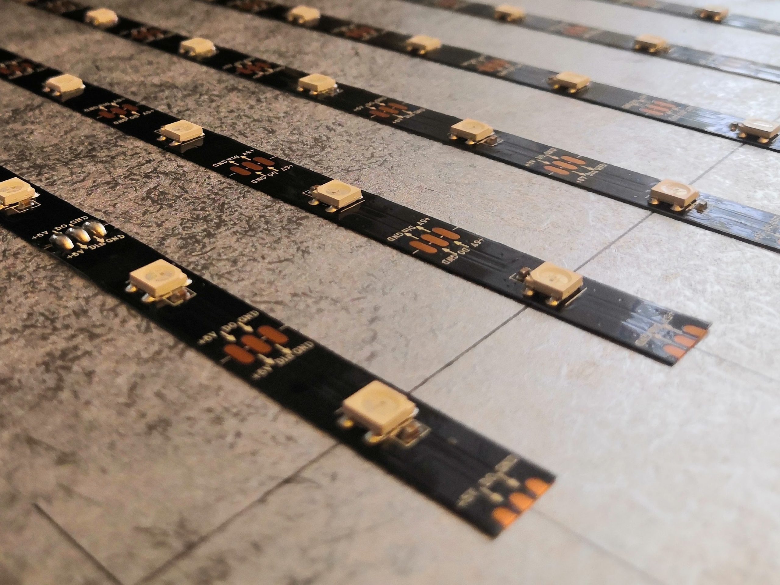
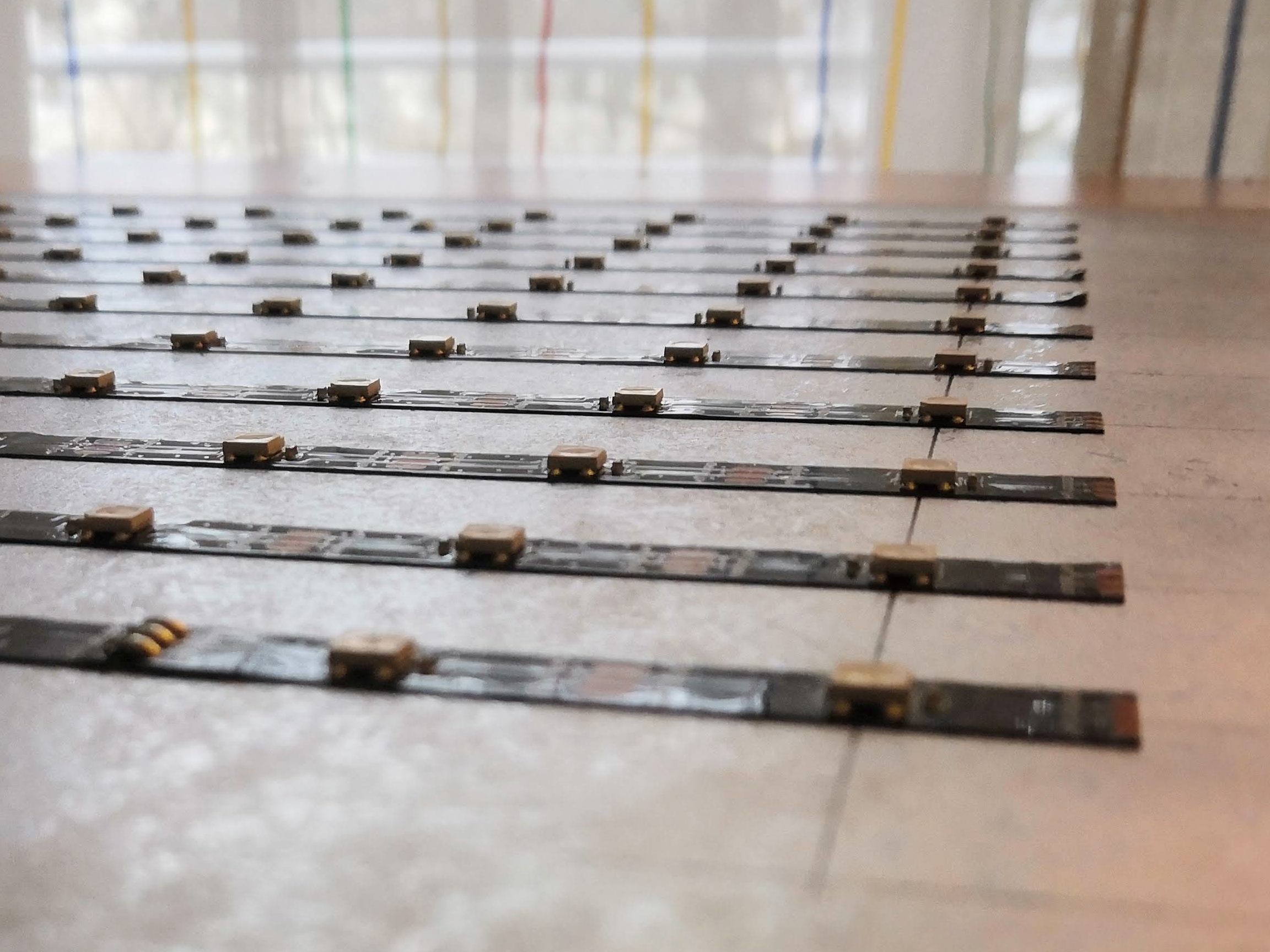
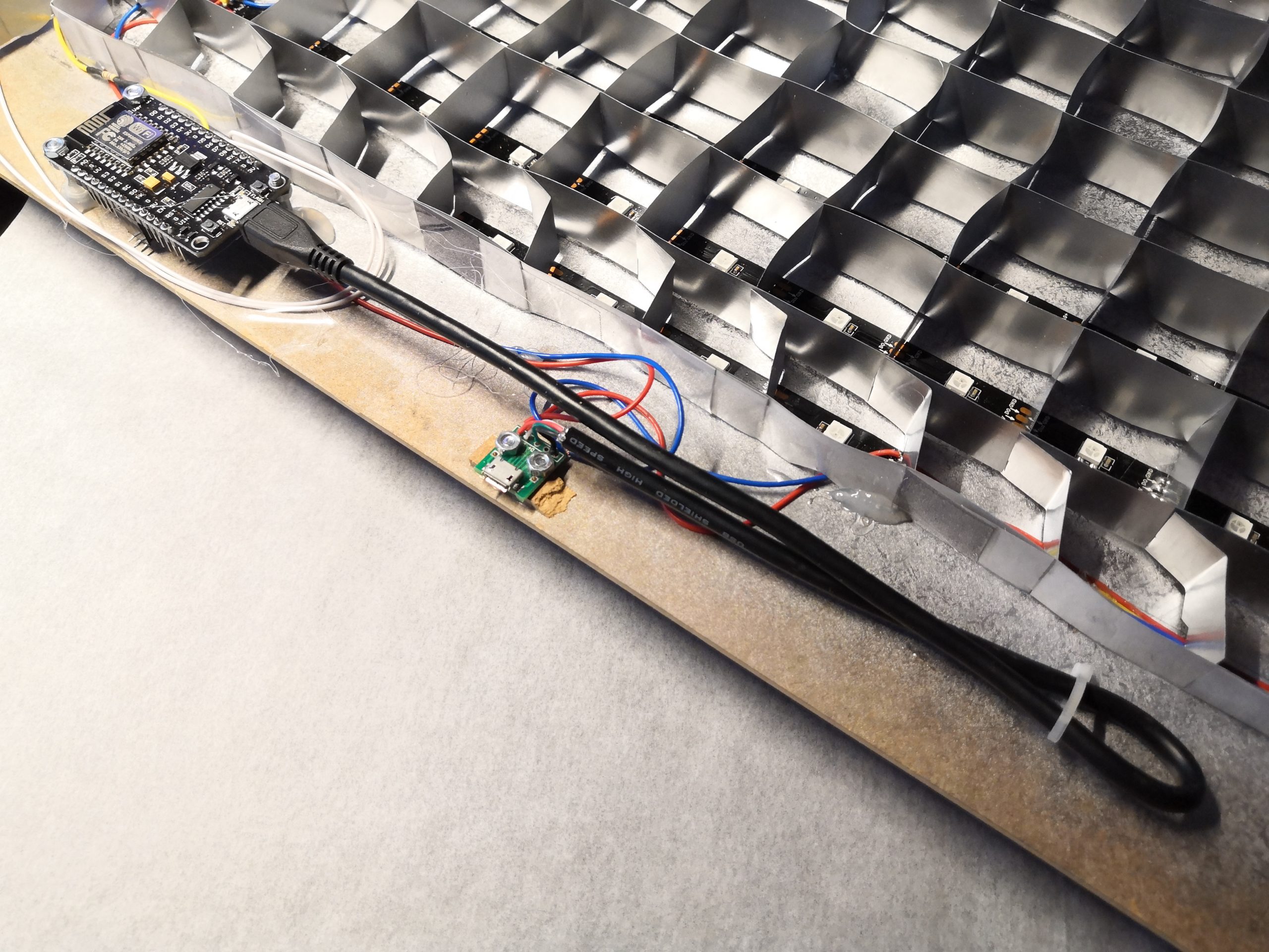
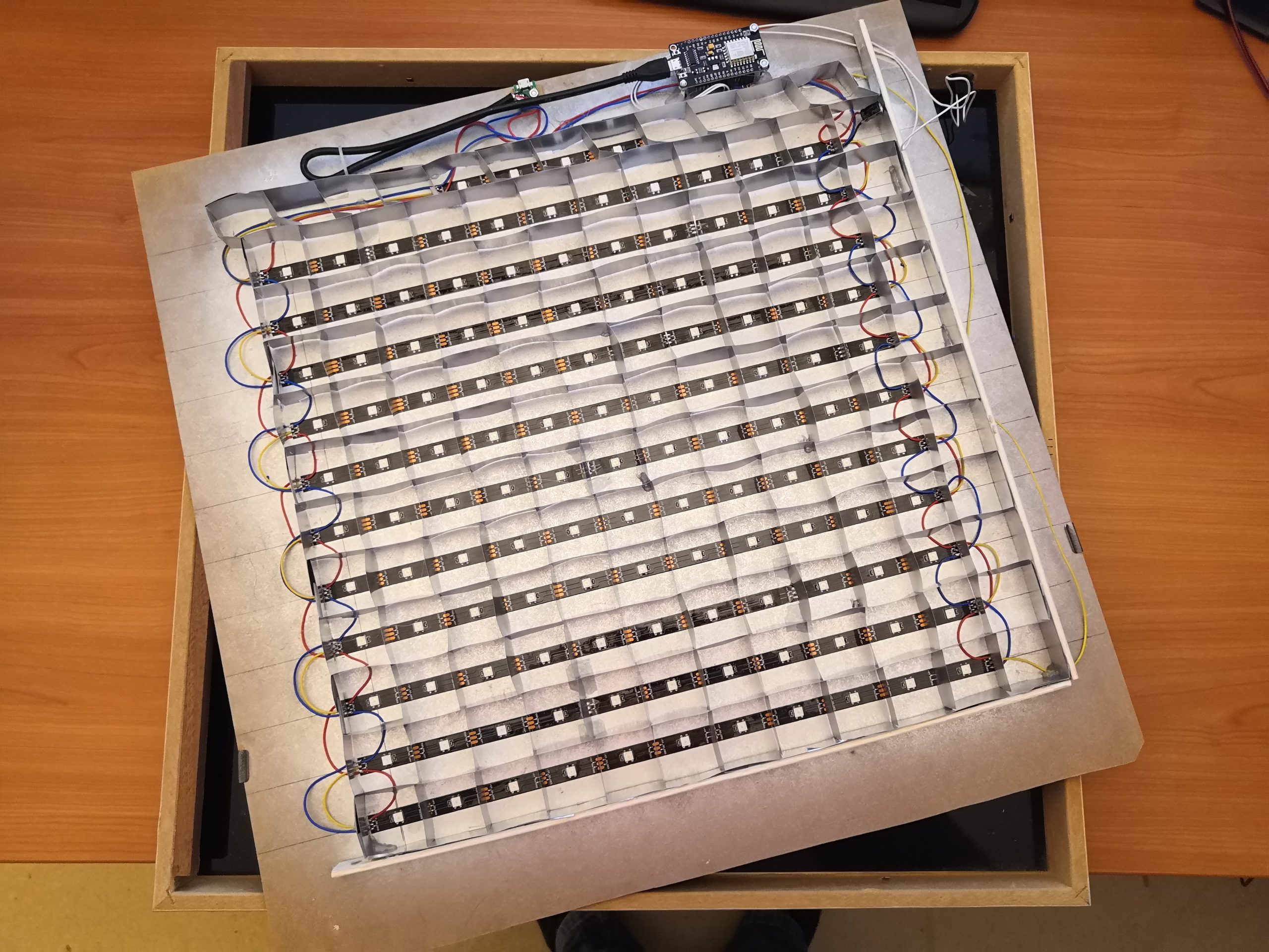
To make the LED matrix, I first divide the long LED strip into 11 strips of 11 LEDs. Then I glued them at a distance of 33mm on the back of the picture frame. I recommend drawing a grid of lines to place the LED strips correctly. As you can see in the pictures below, I spray painted the back with silver/mirror paint to improve the reflections later (You may notice, that in the first version I painted it black to avoid reflection. This time I try it with the mirror color to improve the uniform illumination of the individual letters).
As the twelfth row, I added four additional LEDs, which will later show the minutes on my clock. Very important for the placement is the direction of how the LED strips are arranged. For efficient wiring, a ZIC-ZAC arrangement as shown in the picture is the best.
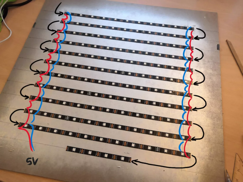
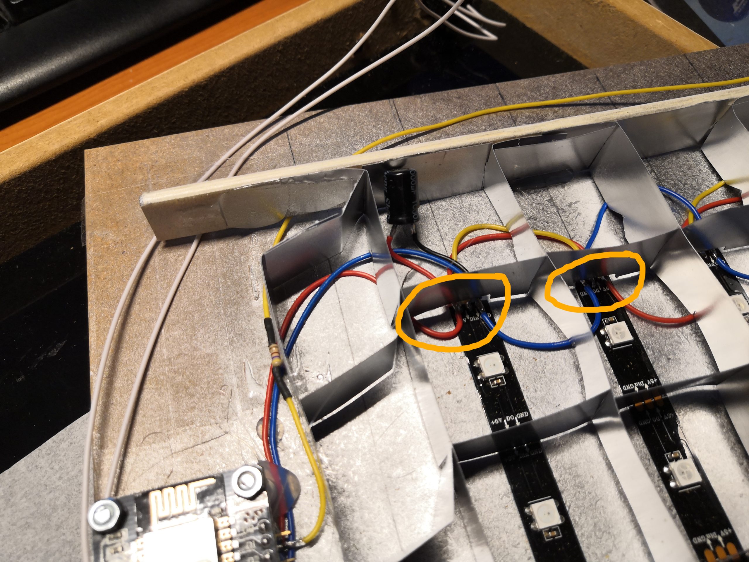
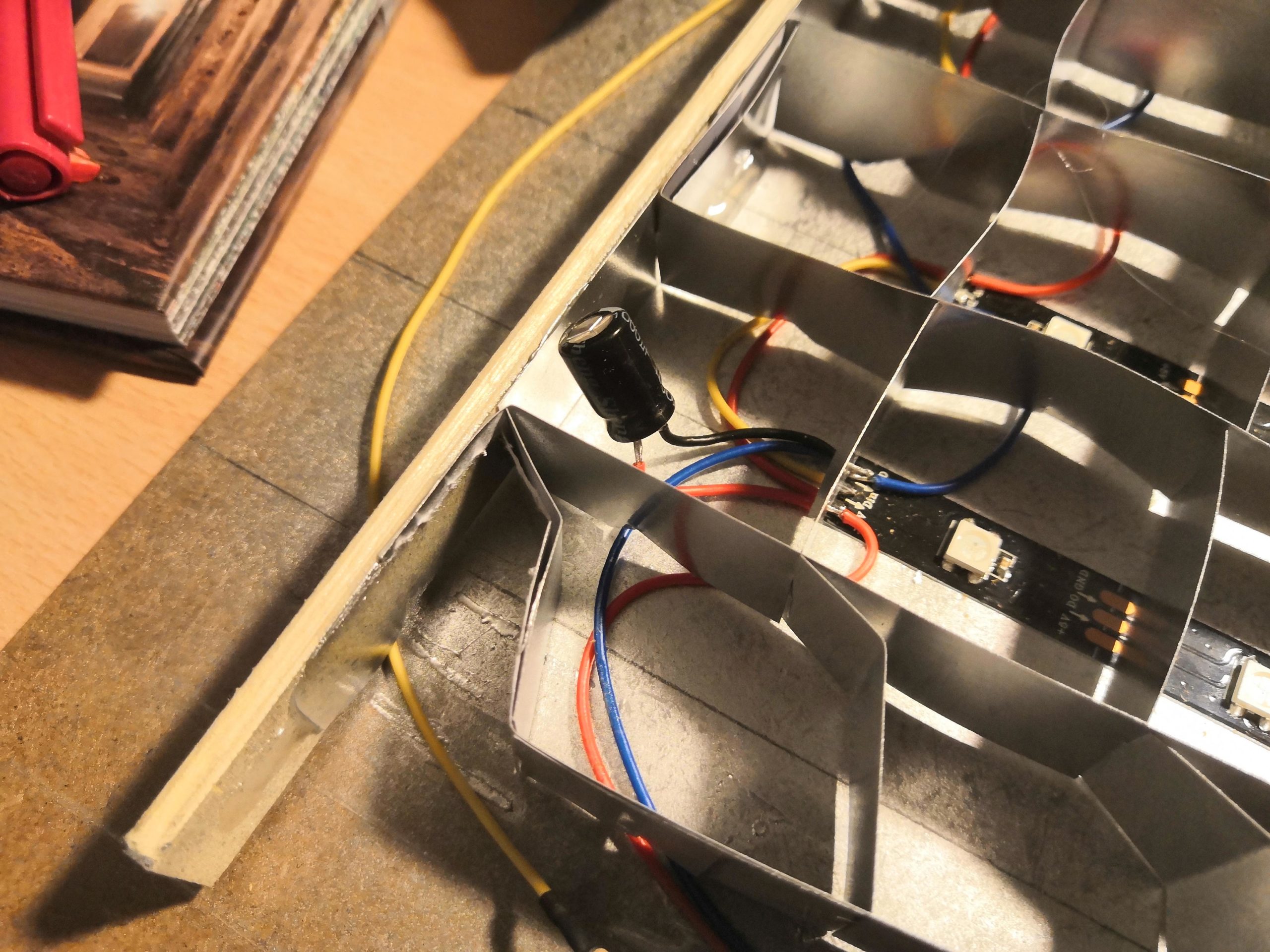
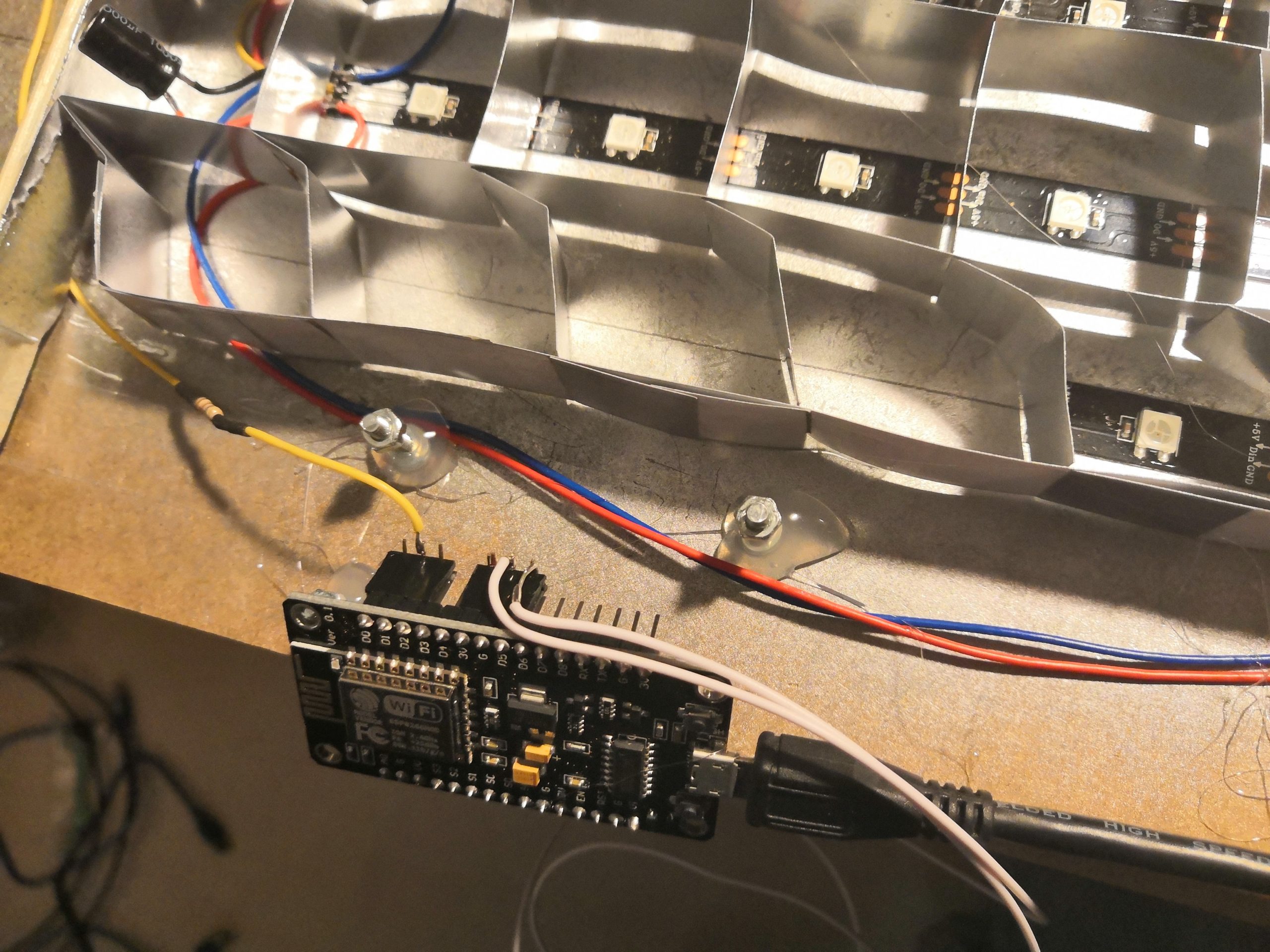
The wiring is not complicated only a bit complex. First I soldered the data line in the ZIC-ZAC pattern so that each DO pin is connected to the next DI pin. Then I soldered all GND and 5V contacts together.
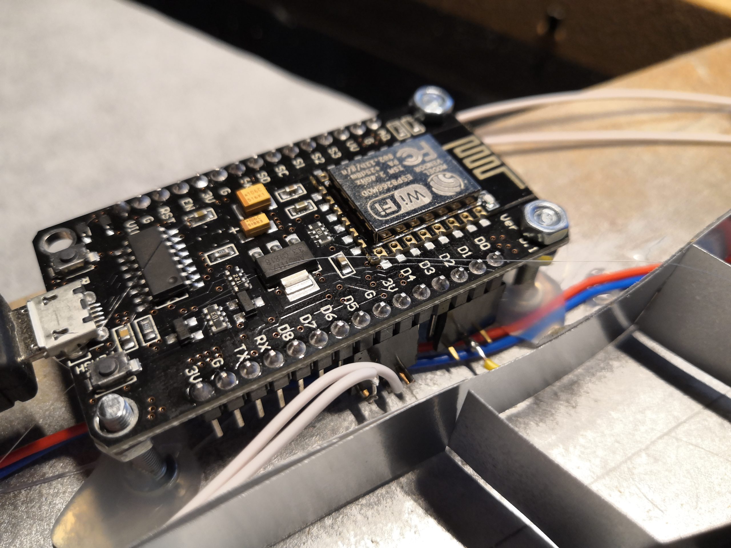
The other electronic components are very manageable. Of course, we need the ESP8266 microcontroller (ESP8266 NodeMCU V3) as the brain of the whole thing, which already has a WLAN interface integrated. Besides that, I only added a 1000 uF capacitor, a 470 Ohm resistor, a push button, and a micro USB connector. The following schematic shows the complete wiring:
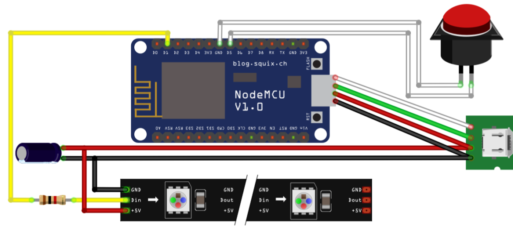


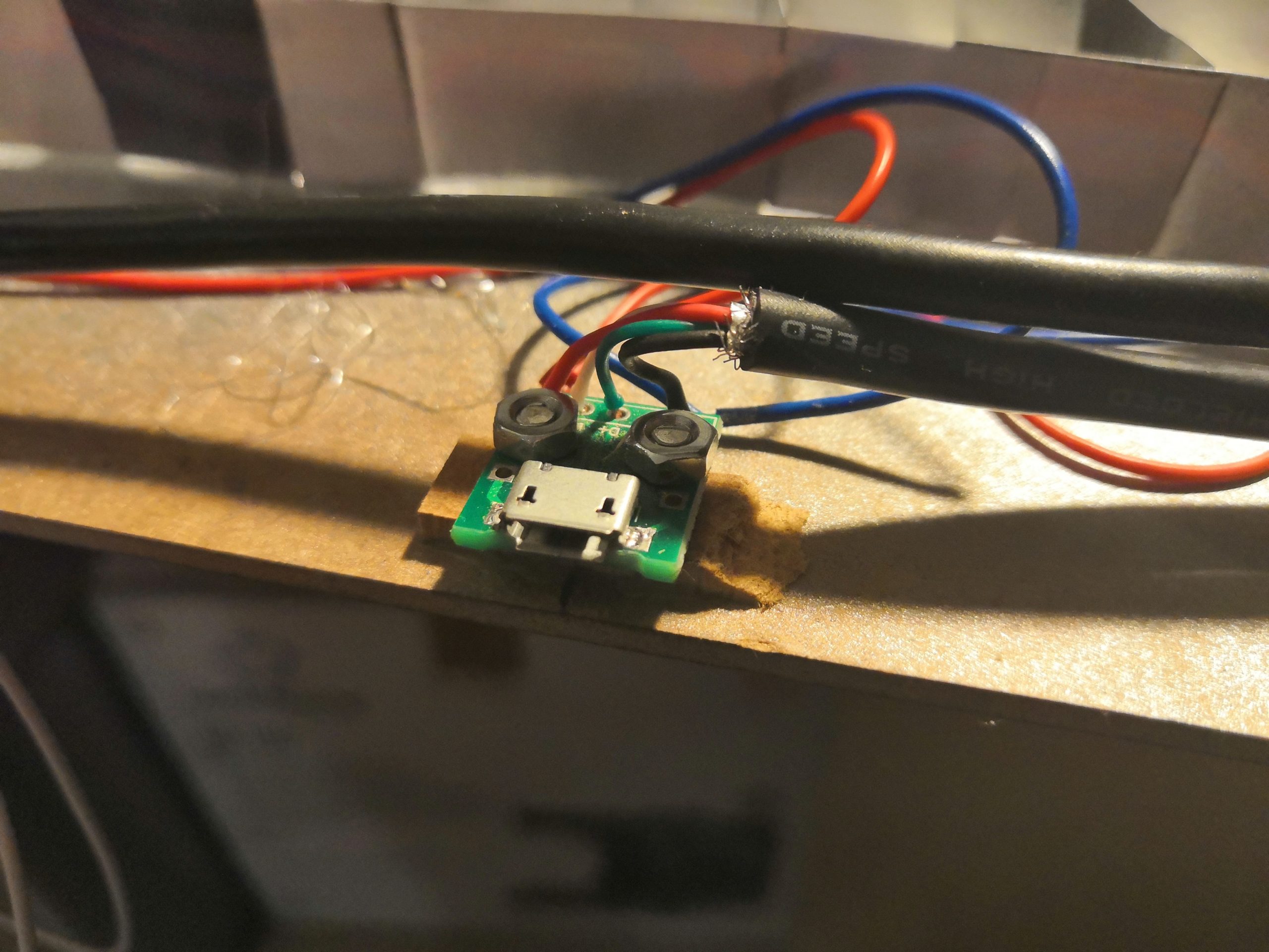
As you can see in the pictures below, I use a micro USB cable to connect the ESP8266 to the micro USB socket. This allows me to program the ESP8266 from outside via the USB socket.
STEP 5: Bring everything together
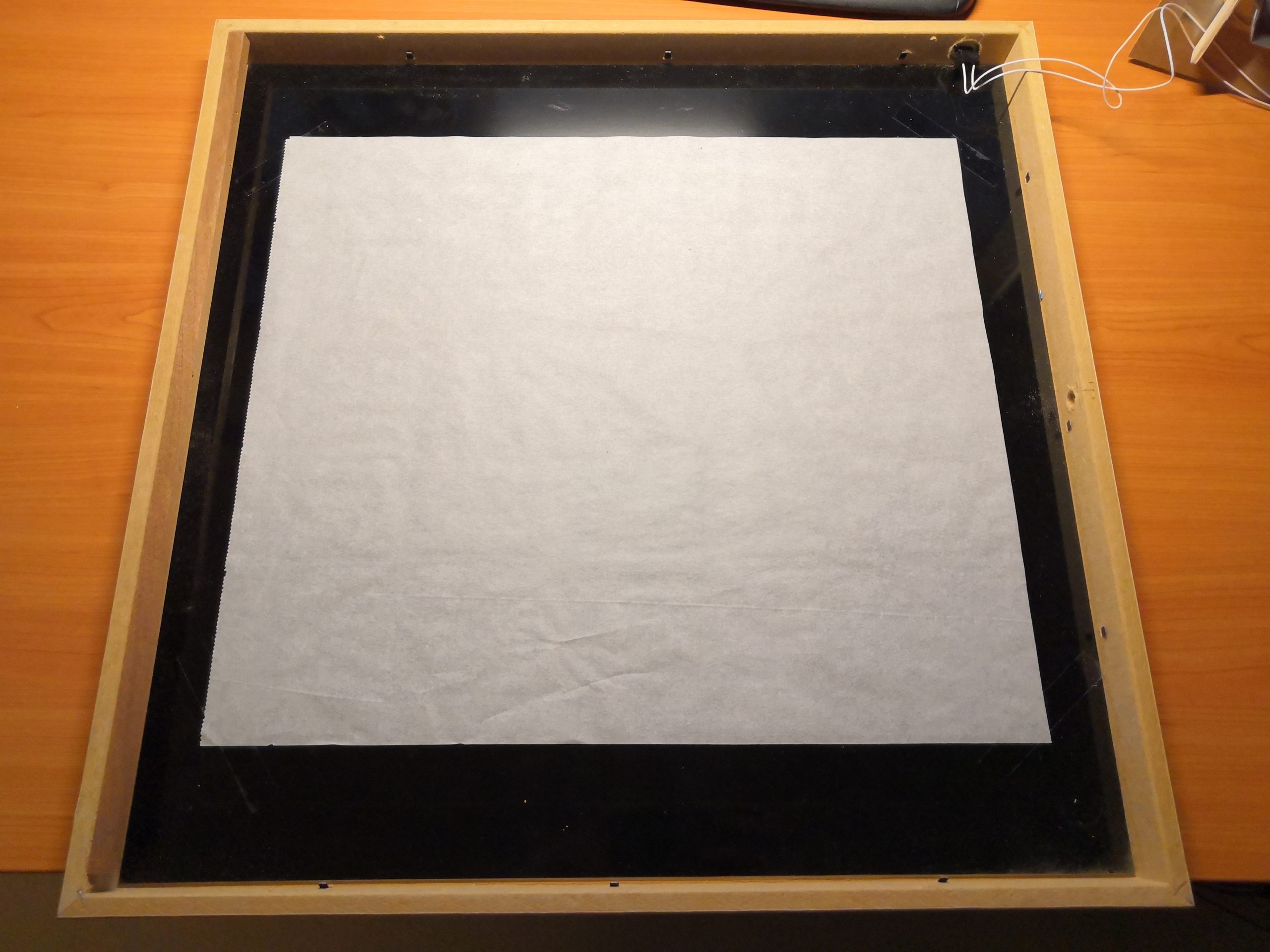
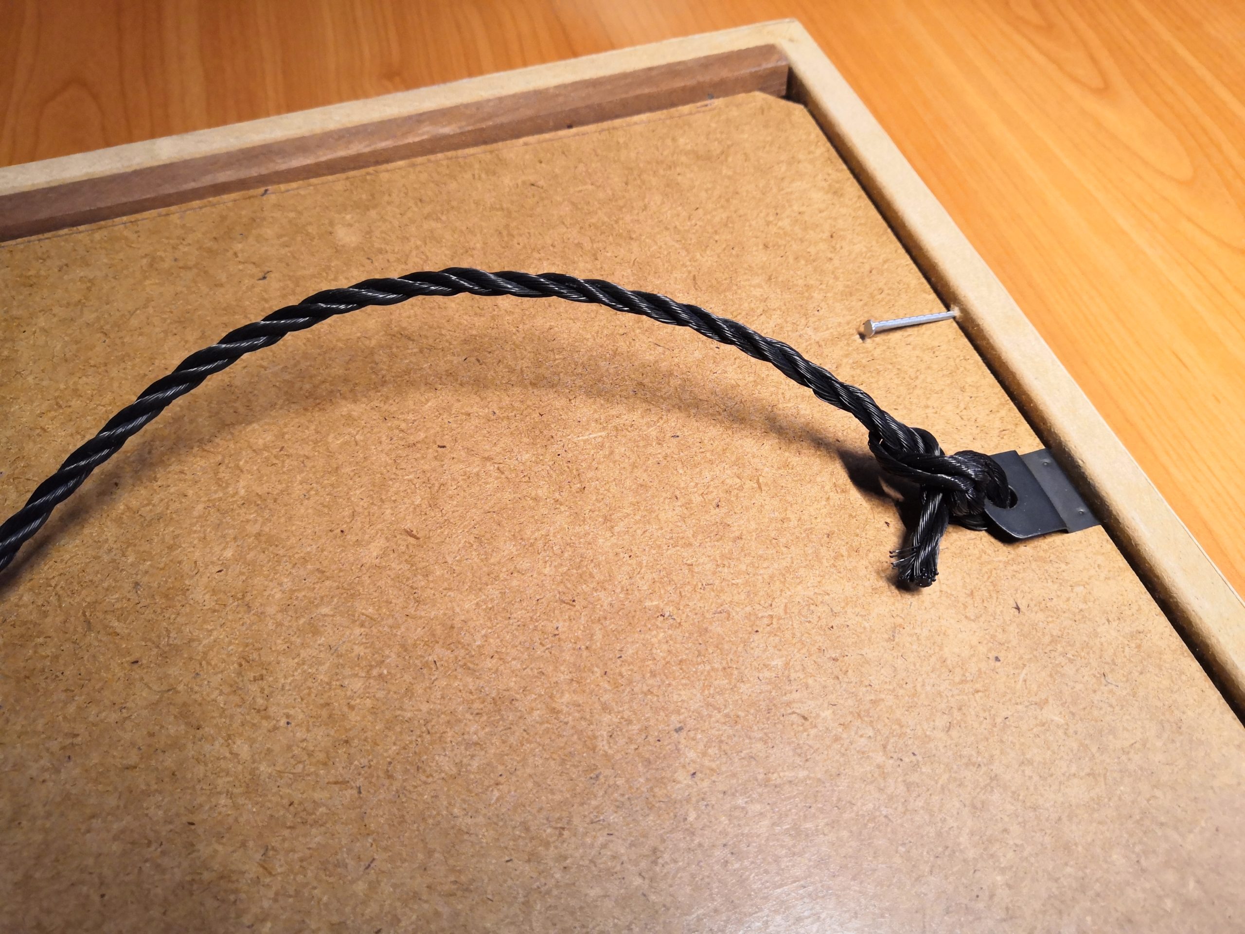
In the final step, I stick a sheet of white backing paper on the back of the glass plate. This results in the wanted diffuse illumination of the individual letters. I glued the light grid with hot glue on the backplate with the LEDs so that everything becomes a solid composition. Now the backplate only needs to be mounted in the picture frame and fastened with four nails.
3. Look at the Heart: The Software
Quickstart
For those who want to get started directly with the code, you can find the complete source code on GitHub:
techniccontroller / wordclock_esp8266
ESP8266 source code for Wordclock 2.0 on GitHub
- Just clone the project into the sketch folder of the Arduino IDE,
- Rename the file example_secrets.h to secrets.h. You don’t need to change anything in the file if you want uses the normal WiFi setup with WiFiManager (see section “Remark about the WiFi setup” in the README.md).
- Install the additional libraries and flash it to the ESP8266 as usual.
- The implemented WiFiManager helps you to set up a WiFi connection with your home WiFi -> on the first startup it will create a WiFi access point named “WordclockAP”. Connect your phone to this access point and follow the steps which will be shown to you.
- After a successful WiFi setup, open the browser and enter the IP address of your ESP8266 to access the interface of the webserver.
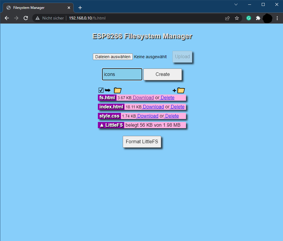
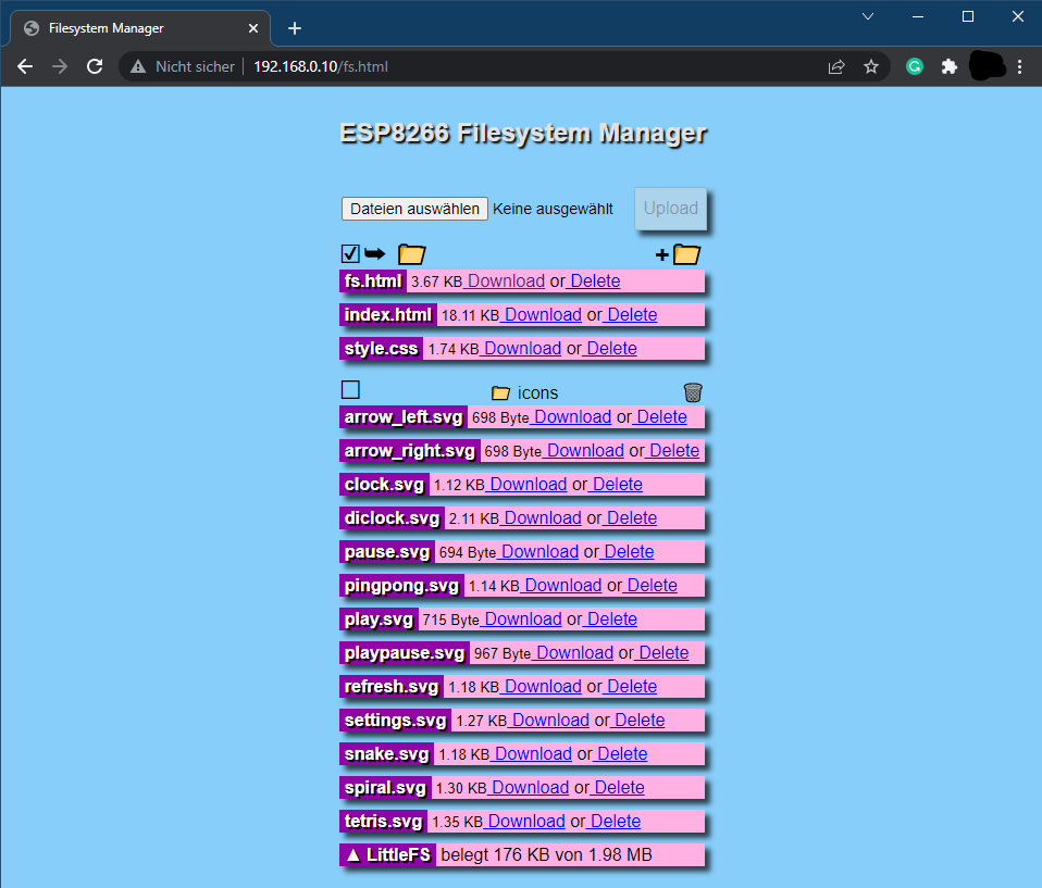
- Here you can then upload all files located in the folder “data”. Please make sure all icons stay in the folder “icons” also on the webserver. The steps for uploading the files should be:
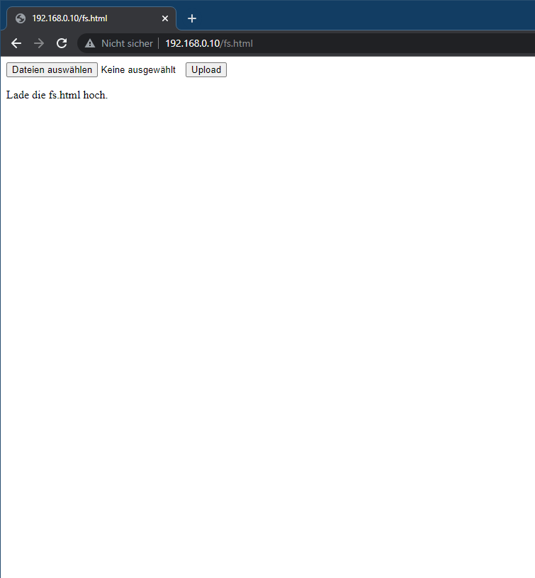
- Open http://<ip-address>/fs.html in a browser
- Upload fs.html
- Upload style.css
- Upload index.html
- Create a new folder icons
- Upload all icons into this new folder icons
The word clock is now ready. Navigate to http://<ipaddress>/ or http://wordclock.local/ to open the web server interface of the word clock and have fun with it!


Detailed Look
For all others, who want to know more about the software, I would like to explain the different functions in detail. I have rarely developed such a structured Arduino project and it’s worth inspecting the code :). The whole code is well documented.
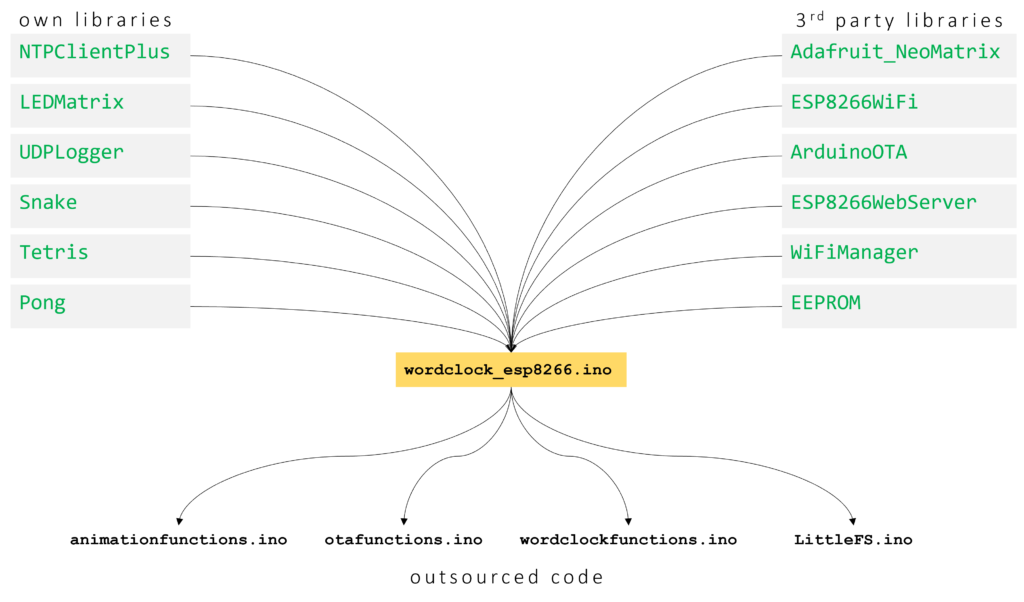
OWN LIBRARIES
NTPClientPlus
Handles all the NTP update stuff, like getting a new time update, converting it to the correct timezone, calculating summer- or wintertime, and splitting the time up in hours, minutes and seconds.
LEDMatrix
Handle all functions related to turning on or off any LED in the Matrix. Provides functions for drawing single pixels, numbers, or characters on the matrix.
It has a low-pass filter function implemented to create smooth transitions between different LED images on the Matrix. The algorithm for that is quite simple. The filtered (to be displayed) color value of a pixel will be calculated like this:
factor = [0...1]
filteredValue_R = currentValue_R + factor * (newValue_R - currentValue_R)
filteredValue_G = currentValue_G + factor * (newValue_G - currentValue_G)
filteredValue_B = currentValue_B + factor * (newValue_B - currentValue_B)
Another neat feature is the LED current limiting and automatic dimming function, which I have implemented in this class. Before writing the color values to the LED strip, the code estimates the total current which is needed to display the given pattern. If the estimated current is above the configurable current limit, it will automatically reduce the overall brightness to meet the total current limit. The code snippet is shown below:
// Calc estimated current (mA) for one pixel with the given color and brightness
uint16_t LEDMatrix::calcEstimatedLEDCurrent(uint32_t color){
  // extract rgb values
  uint8_t red = color >> 16 & 0xff;
  uint8_t green = color >> 8 & 0xff;
  uint8_t blue = color & 0xff;

  // Linear estimation: 20mA for full brightness per LED
  // (calculation avoids float numbers)
  uint32_t estimatedCurrent = (20 * red) + (20 * green) + (20 * blue);
  estimatedCurrent /= 255;
  estimatedCurrent = (estimatedCurrent * brightness)/255;

  return estimatedCurrent;
}

// Draws the targetgrid to the ledmatrix
void LEDMatrix::drawOnMatrix(float factor){
  uint16_t totalCurrent = 0;
  // go over all leds in matrix
  for(int s = 0; s < WIDTH; s++){
    for(int z = 0; z < HEIGHT; z++){
      // inplement momentum as smooth transistion function
      uint32_t filteredColor = interpolateColor24bit(currentgrid[z][s], targetgrid[z][s], factor);
      (*neomatrix).drawPixel(s, z, color24to16bit(filteredColor));
      currentgrid[z][s] = filteredColor;
      totalCurrent += calcEstimatedLEDCurrent(filteredColor);
    }
  }

  // minutes indicator leds
  for(int i = 0; i < 4; i++){
    uint32_t filteredColor = interpolateColor24bit(currentindicators[i], targetindicators[i], factor);
    (*neomatrix).drawPixel(WIDTH - (1+i), HEIGHT, color24to16bit(filteredColor));
    currentindicators[i] = filteredColor;
    totalCurrent += calcEstimatedLEDCurrent(filteredColor);
  }

  // Check if totalCurrent reaches CURRENTLIMIT -> if yes reduce brightness
  if(totalCurrent > currentLimit){
    uint8_t newBrightness = brightness * float(currentLimit)/float(totalCurrent);
    (*neomatrix).setBrightness(newBrightness);
  }
  (*neomatrix).show();
}
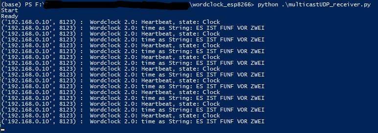
UDPLogger
As the ESP8266 is most of the time not connected to a computer, it would be convenient to still have some information about what the controller is currently doing. I created this library already for previous projects. With this library, you can easily send UDP multicast messages into the network and everyone in the network can receive these messages. I wrote a small python script (multicastUDP_receiver.py) that can receive and display the messages.
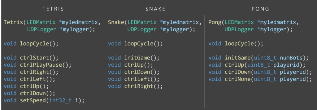
Snake, Tetris, Pong
All these classes are structured similarly. They contain the algorithm for the games which can be played via controls from the webserver. So each class has some update function, which is called in every cycle to draw potentially new pixels on the matrix. Also, each class has one or more control functions which can be called when the user triggers some action from the web server interface (e. g. turn left, turn up, rotate,…).
OUTSOURCED CODE
animationfunctions.ino
In this file, I moved all functions, which are needed for the animation. So for example the SPIRAL animation and the animations for the random SNAKE or TETRIS game (if the clock is set to automatic state-changing mode, the different game states will show a random animation of their game). In the outsourced functions, I used as few as possible global variables, so if a variable needs to be available for the next execution of the function, I used static variables.
otafunctions.ino
Contains all the functions needed to set up ArduinoOTA updates. Is just the setupOTA() and handleOTA() function. Nothing fancy, just to get this standard code out of the main file.
wordclockfunctions.ino
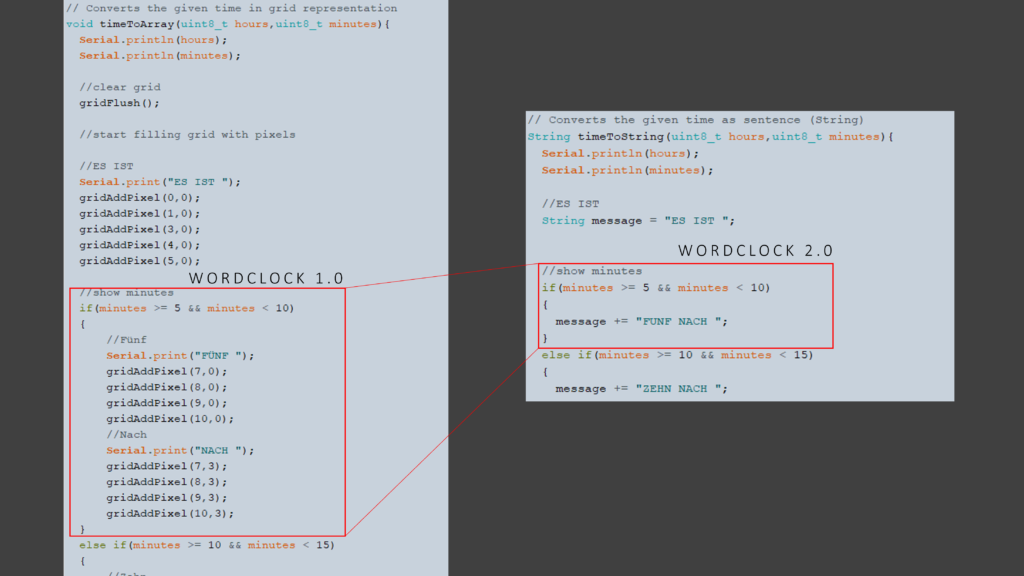
This file contains some interesting functions. Most of the word clocks out there uses some kind of direct mapping from time values (hour and minute) to LED coordinates on the word clock. One disadvantage is that when you change the layout of the word clock (e. g. more rows, more columns, another language, …) you need to do the whole mapping again. I did this in my first version as well and had to deal with a lot of x and y coordinates.
This time I use a different approach, instead of doing a mapping from time to coordinates, I split this task up into two parts. Firstly, a mapping from time value to words (or sentence) and secondly a mapping from words (or sentence) to coordinates. The first mapping is still a little bit of work, but instead of dealing with coordinates, you can easily write down the strings that correspond to the specific time value. In the following picture, you can see a short comparison of the code amount of both approaches.
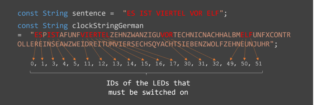
What about the second mapping? The great thing about the seconds mapping is that we can implement it completely generic. This means if we have a string representation of the whole word clock, we can easily fit a given sentence in it and so automatically identify which LEDs need to be switched on. An example is shown in the figure below.
LittleFS.ino
This file is an unchanged takeover from https://fipsok.de/Esp8266-Webserver/esp8266. It provides a very nice file manager for the easier upload of files to ESP8266.
FAQ – Customization
What do I have to change if I use a different layout or a different language?
The Wordclock is available in German, English, and Italian language. By default the language is German. To use the English or Italian language please replace the file wordclockfunctions.ino with wordclockfunctions.ino_english or wordclockfunctions.ino_italian. The code compiles only with one file named wordclockfunctions.ino. So please rename the file you want to use to wordclockfunctions.ino and replace the existing file.
To use a custom layout, you have to do the following:
• in the wordclockfunctions.ino change the variable clockStringGerman according to your layout.
• in the wordclockfunctions.ino change the function timeToString() so that your wished sentence (e. g. “IT IS ONE OCLOCK”) is created based on the given hours and minutes value.
What do I have to change if I use only 10 rows instead of 11?
You have to do the following (But keep in mind that due to the letter size, the digital clock mode does not look good with only 10 rows):
• in ledmatix.h, tetris.h and wordclock_esp8266.ino change the line
#define HEIGHT 11to
#define HEIGHT 10• in pong.h and snake.h change the line
#define Y_MAX 11to
#define Y_MAX 10• in the wordclockfunctions.ino change the variable clockStringGerman according to your layout.
• in ledmatrix.cpp change the line
(*neomatrix).drawPixel(WIDTH - (1+i), HEIGHT, color24to16bit(filteredColor));to
(*neomatrix).drawPixel(i, HEIGHT, color24to16bit(filteredColor)); (this needs to be changed, as the minute indication LEDs are now at the beginning of the last row instead of the end).
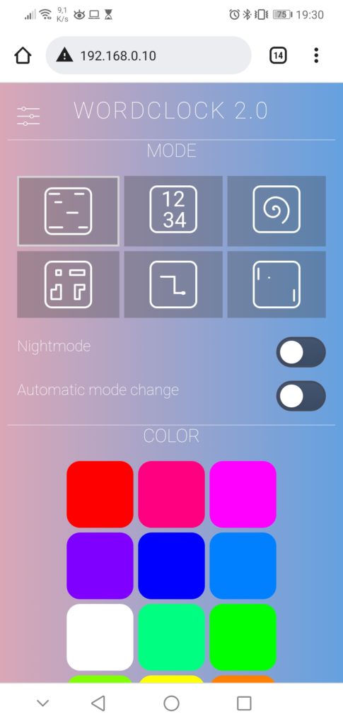
Modes of the word clock
One can change the different modes by a short press on the physical push button in the picture frame or by selecting it in the web interface. In the web interface, there is also the option to enable an automatic mode change every 10 seconds. If this function is active the game modes TETRIS, SNAKE and PONG will just play an animation without user interaction.
I additionally implemented a night mode that turns off all LEDs. The clock enters night mode at a specific time, which can be configured in the settings menu of the web interface. The night mode can also be activated at any time directly via the web interface or a long press on the physical push button.
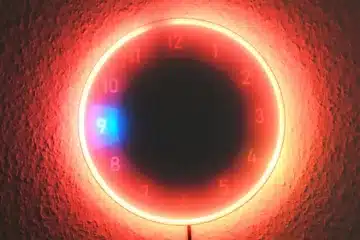
Word clock
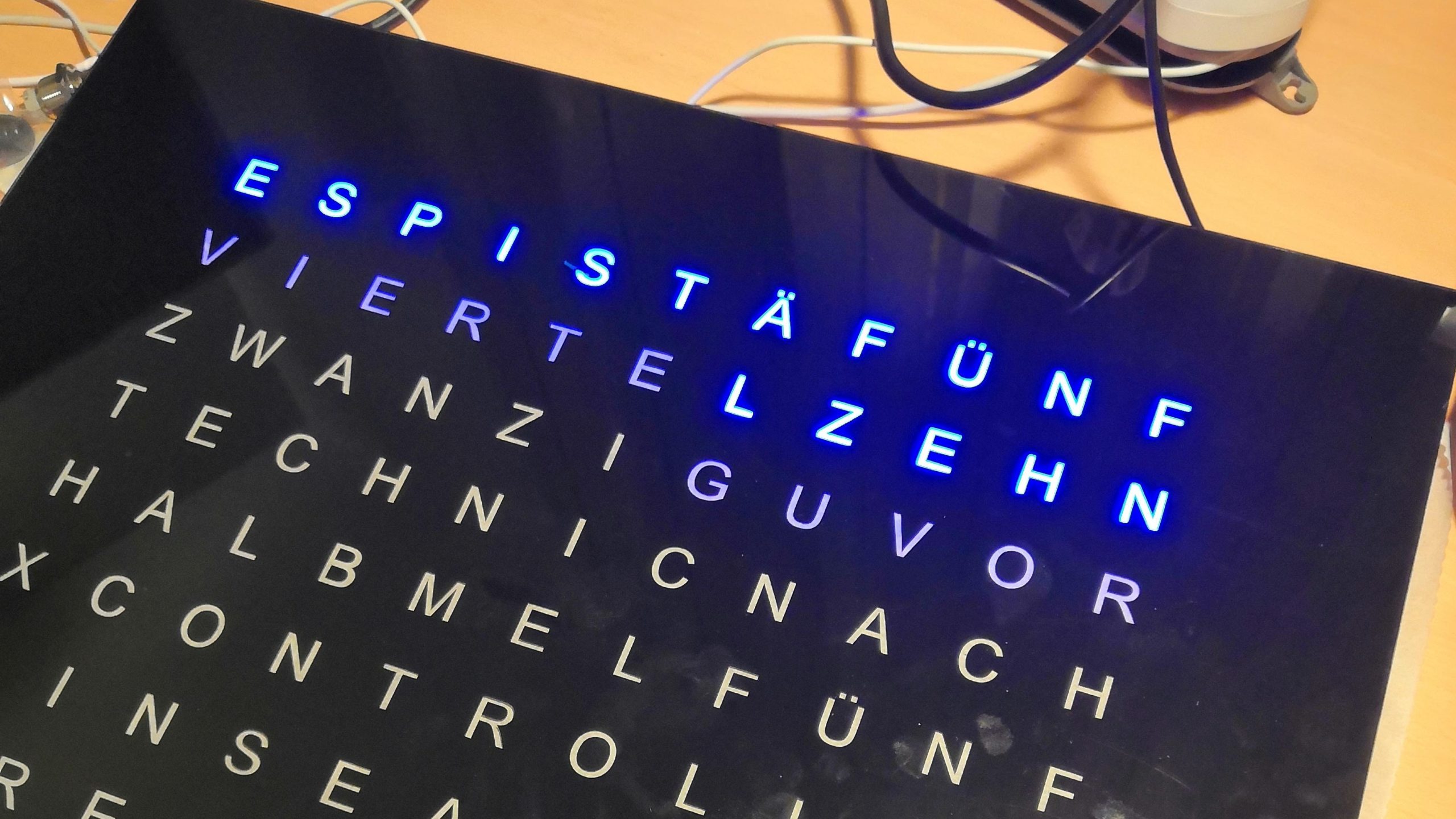
Standard mode which is active after startup is of course the normal word clock mode, where the clock displays the time as text.
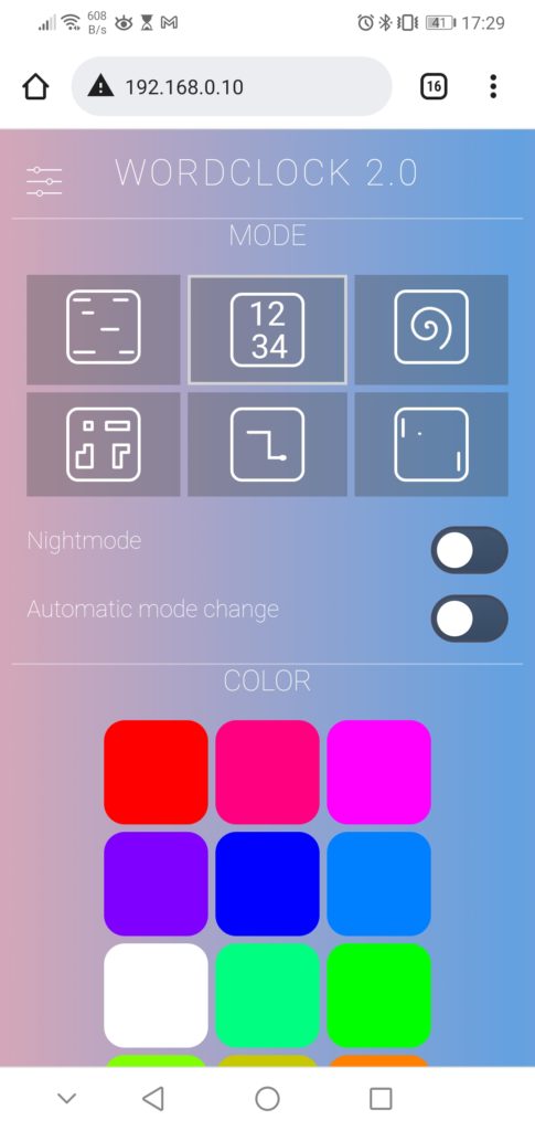
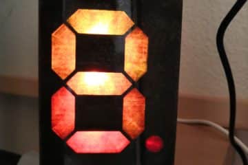
Digital clock
The second mode also displays the time, but as digits drawn on the LED matrix. This is only possible because of the 11th row so that I can construct two lines of 5 row high digits with one empty line in between.
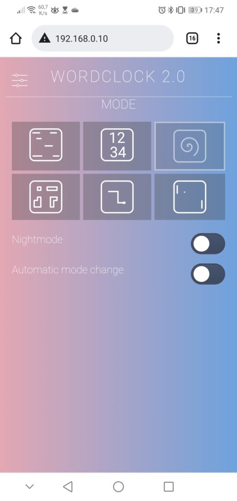
SPIRAL animation
In this mode, the clock displays a spiral animation with changing colors.
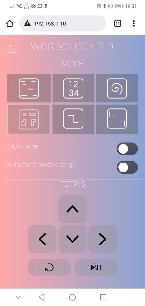
TETRIS game
Tetris is one of three game modes, which can be controlled via the web interface. I have not written the core game code of those three games completely myself. Instead, I used some code parts from here as a basis and integrated them into my object-oriented software. The code for the random animation of Tetris and Snake is a takeover from my previous LED-Matrix project.
SNAKE game
Here you can control a snake to catch the randomly placed apple. Well, just the traditional Snake game, I don’t think I need to explain much more.

PONG game
For Pong, you need usually two players. But, I extended the code by a bot that can control just one or both paddles. So the user can control the right paddle via the web interface or let the bot take over the paddle movement in case of the animation mode.
Have fun rebuilding it! If you have any questions, please feel free to write a comment.
161 Comments
Thomas · 13/02/2024 at 20:49
Hallo Edgar,
ich habe seit langem nach einem Projekt für eine „Wortuhr“ gesucht. Dein Projekt war meiner Meinung nach das Beste und ich habe sofort angefangen es umzusetzen. Die Uhr hat auf Anhieb funktioniert.
Leider habe ich einen kleinen Fehler. Die Uhr bleibt nach einem halben bis 2 Tagen stehen und es leuchten die 4 Minuten LED in blau dauerhaft.
Ich habe eine zweite gebaut und auch diese bleibt nach einiger Zeit stehen.
Hast du eine Idee, wo der Fehler sein kann?
Schon jetzt vielen Dank für deine Hilfe.
Gruß Thomas
Techniccontroller · 13/02/2024 at 21:33
Hallo Thomas,
danke für dein Kommentar. Es freut mich, dass dir mein Projekt gefallen hat.
Die Symptome sehen danach aus als würde die Uhr sich nicht mehr mit dem WLAN verbinden können. Die Uhr holt sich im normalen Betrieb alle 30 Sekunden die aktuelle Uhrzeit von einem NTP-Server aus dem Internet. Falls dieses Update innerhalb von 5 Minuten nicht mindestens einmal erfolgreich ist, startet die Uhr neu. Falls es nun Probleme bei der erneuten Verbindung mit dem WLAN gibt, bleibt die Uhr mit deinen beschrieben Symptomen beim Start hängen.
Ich würde daher einemal sicherstellen, dass dein WLAN stabil ist und der Empfang für die Uhr gut ist. Du kannst das Intervall für den Restart (5min) auch erhöhen, falls deine Internetverbindung bekanntlich unzuverlässig ist. Dazu musst du nur in Zeile 548, den watchdogCounter auf eine höhere Zahl setzen (z.B. auf 60 für 10 min).
Ich hoffe das hilft dir erstmal weiter.
Viele Grüße
Edgar
Thomas · 13/02/2024 at 21:38
Vielen Danke für die schnelle Anwort.
Ich werde es testen.
Gruß Thomas
Yuri · 03/02/2024 at 22:12
Herzlichen Glückwunsch zum Projekt.
Ich versuche es auf Italienisch zu machen.
Alles funktioniert, außer dass die Worte “SONO LE” nicht aufleuchten.
Ich bin mit Arduino nicht sehr vertraut, ich habe versucht, Code zu verstehen, aber ich kann die Lösung nicht finden. Kannst du mir helfen. Danke
Techniccontroller · 03/02/2024 at 23:44
Hallo Yuri,
danke für deinen Kommentar.
Aus der Ferne kann ich schwer sagen was nicht stimmen kann. Kannst du vielleicht mal die Ausgabe auf dem Seriellen Monitor beobachten und prüfen ob die Uhrzeit korrekt in einen Satz konvertiert wurde. Ist hier also das “SONO LE” vorhanden?
Nutzt du das Layout, welches ich im timeString vorgeschlagen habe oder hast du ein eigenes Layout? Wenn ja musst du prüfen ob die Buchstaben für SONO LE auch in deinem Layout als erstes kommen, bevor andere Worte im Layout platziert sind.
Ich hoffe das hilft dir erstmal weiter. Wenn ich nochmal genauer helfen soll, bräuchte ich mehr Infos, wie zum Beispiel den Code und die Ausgabe des seriellen Monitors.
Viele Grüße
Edgar
Alessandro Brigida · 04/02/2024 at 1:51
Ciao Yuri “sono le” si accende solo per il cambio orario ovvero tutte le ore con gli zeri, esempio: “è l’una”, “sono le due” ecc. per tutti gli altri orari si leggerà solo l’orario senza la parte del “sono le”. Spero di esserti stato utile. Spero che Edgar possa capire la mia risposta e confermarla.
Alessandro
Yuri · 04/02/2024 at 18:29
Ciao Alessandro grazie per per aver risposto.
Ho appena controllato quando fa il cambio dalle 17.59 alle 18.00, si accende solo “sei”, “sono le” rimane spento. Non ho ancora ben chiaro se questo sia giusto e “sono le” si accenda solo con gli orari mattutini(tipo le 06.00).
Inoltre dopo un po’ (tipo 20/30min) i monitor seriale non si aggiorna più, e l’orario risulta essere di un ora avanti senza che io abbia toccato nulla. Riapro il seriale e nonostante time sia per esempio 18.25 time as string risulta essere sette e venticinque.
Techniccontroller · 04/02/2024 at 19:05
Hi Yuri,
I rechecked the code and found a big mistake in the function timeToString() for the Italian version.
Please check the code on GitHub again and update your code with the fix:
https://github.com/techniccontroller/wordclock_esp8266/commit/c1cafa56f2c4b6c32f7f4df806e558db8b57cf96
Please test the new version, and give feedback if now everything works as expected.
Best regards
Edgar
Yuri · 05/02/2024 at 1:30
Everything works much better. There is still a small error. When it is 12.35 “SONO LE ” lights up, only when it is 1.00 “È L’ ” lights up. I tried to understand the code and actually the if part of “SONO LE/ È L’ be right. I can’t understand the error.
Techniccontroller · 05/02/2024 at 7:26
Hi Yuri,
Yeah, there was still minor bug. I fixed it:
https://github.com/techniccontroller/wordclock_esp8266/commit/4b40f55254b7962ea2d2389e13af13197589c5a4
Now it should work.
Best regards
Edgar
Stratis · 23/01/2024 at 22:28
Hi
Want to translate the front plate in Greek
Can you let me know the things i need to pay attention in the SW as i do not have the detail knowledge of Arduino programming.
Tks
Techniccontroller · 23/01/2024 at 22:55
Hi Stratis,
thank you for your comment.
As I have described in the FAQ section above (“What do I have to change if I use a different layout or a different language?”), you just need to change two things in the code, first the variable timeString according to your layout (just the letters row by row) and the function timeToString(), which includes the logic to convert two numbers (hour and minutes) into a sentence (String) representing the time.
You can look at the English version of how it is done and adapt it to Greek.
As you have the Greek alphabet, where letters can not be represented by one-byte large ASCII codes I would suggest, that you represent each Greek letter with a letter from the English alphabet. Otherwise, the algorithm may have a problem visualizing the string on the clock.
For example:
Alpha (Α α) -> English equivalent: A
Beta (Β β) -> English equivalent: B
Gamma (Γ γ) -> English equivalent: G
Delta (Δ δ) -> English equivalent: D
Epsilon (Ε ε) -> English equivalent: E
Zeta (Ζ ζ) -> English equivalent: Z
Eta (Η η) -> English equivalent: H
Theta (Θ θ) -> English equivalent: T
Iota (Ι ι) -> English equivalent: I
Kappa (Κ κ) -> English equivalent: K
(….)
I hope that helps you as a starting point. If you have more questions, don’t hesitate to ask.
Best regards
Edgar
Cyprien · 23/01/2024 at 15:30
Hello,
Many thanks for this wonderful project.
I have built the clock and it seems to work correctly. However, I am in the process of modifying the wordclock.ino code to make the clock work in French.
Not being an expert in programming, I still have a few periods that are not displayed correctly.
Is it possible to bypass the web server for the time and manually enter the time to be written to the application so that I can test the code and the changes?
Thanks in advance.
P.S. If you want to publish the code in French once it’s up and running, can you tell me how to send it to you?
Translated with DeepL.com (free version)
Techniccontroller · 23/01/2024 at 22:11
Hi Cyprien,
thank you for your comment.
Yes, you can bypass the NTP time, by sending a time via the webserver to the clock to test your algorithm. For that, you need to change some lines in the code. I quickly created a new branch with the change, which you can adapt in your code.
GitHub: https://github.com/techniccontroller/wordclock_esp8266/commit/028a91d6e16a0eabff4fc7945982b18b9e5ea82d
for example, you can now set the time to 10:23 by entering this URL into the browser: http:///cmd?time=10-23
Just one additional hint about the letters in the timeString variable. As the French language has these special characters with an apostrophe like é, you should not use those directly in the timeString variable. Because these are no normal ASCII characters and would distract the algorithm. So please replace them with special characters like ‘+’ , ‘-‘ , ‘#’ or ‘)’ you can have a look at the Italian version, there I did a similar thing.
I am happy to integrate your French version into GitHub, just create an issue on GitHub with the code or send me the code via mail (see imprint).
Best regards
Edgar
Manuel · 06/01/2024 at 19:06
Hallo Edgar,
herzlichen Dank für dieses tolle Projekt. Nachdem ich Version 1 nachgebaut habe, traue ich mich jetzt an diese Variante. Du hast es teilweise sehr detailliert beschrieben, leider nicht immer idiotensicher ;o) Ich hänge derzeit an folgendem Problem.
1.Ich habe das ESP-Modul (
AZDelivery 3 x NodeMCU Lolin V3 Module ESP8266 ESP-12F WiFi CH340) nach Anleitung in Arduino IDE eingebunden, allerdings taucht es nicht in der esp8266-Auswahlliste auf. Ich kann zwar NodeMCU 0.9 oder 1.0 auswählen, weiß aber nicht ob das in Ordnung ist, denn wenn ich dann versuche zu flashen gibt es Fehlermeldungen.
2, Du schreibst “Create a directory named data and any files you want in the file system there” bedeutet das, dass ich dort wo z.B. auch der Ordner “librarie” ist jetzt einen Ordner “data” erstellen muss und alles Zeug von Github da reinlade? Brauche ich dann keine librarie mehr?
3. ich habe dann großzügig in mehreren Ordnern die Dateien abgelegt und Upload gedrückt. Er sagte mir dann, dass WifiManager.h nicht existiert. Ist Deine Zip nicht komplett oder liegt der Fehler woanders? Ich habe dank des Links im Code dann die Dateien runtergeladen und auch in den Ordnern verteilt, was auch geholfen hat. Dann kamen allerdings andere Fehlermeldungen. Z.B. C:\Users….\sketch_jan6a.ino:613:7: error: ‘spiral’ was not declared in this scope; did you mean ‘st_spiral’?
Gestoppt hat er aber erst in Zeilte 320 mit “Compilation error: ‘setupFS’ was not declared in this scope; did you mean ‘setup’?”
Sorry für die Bombardierung mit Fragen und danke für Deine Mühen die Du Dir machst.
Viele Grüße
Manuel
Techniccontroller · 07/01/2024 at 12:27
Hallo Manuel,
danke für dein Kommentar. Ich versuche mal deine Fragen zu beantworten.
Zu 1: Du hast das selbe ESP8266 Modul wie ich verwendet. Das heißt du kannst einfach auch wie ich NodeMCU 1.0 als Board in der Liste auswählen, damit sollte es funktionieren. Schau mal in die README auf GitHub, da hab ich die Schritte detailiert beschrieben.
Zu 2: An die Formulierung, welche du erwähnst kann ich mich nicht erinnern. Du musst weder einen Ordner “data” erstellen noch irgendwo kopieren. Der Ordner “data” existiert bereits wenn du den Code von GitHub herunterlädst. Das einzige was du mit den Dateien in dem Ordner machen musst ist ganz am Ende (wenn du den Code schon auf den ESP geladen hast und die Uhr mit einem WLAN verbunden ist!) diese auf den Webserver des ESP hochzuladen, wie es von mir im Artikel oben beschrieben wurde.
Zu 3: Ich verstehen nicht warum du Dateien verschoben oder kopiert hast. Wenn du den kompletten Code von GitHub herunterlädst und in deinen Sketchordern von Arduino IDE speicherst, dann ist alles schon in der richtigen Struktur. Du musst dann noch die fünf Bibliotheken, welche ich in der README auf GitHub aufgelistet habe, ganz normal über die Arduino IDE installieren. Wenn du die Schritte des Quickstarts durchführst sollte es kompilieren und problemlos auf den ESP8266 hochladen.
Im Allgemeinen würde ich dir empfehlen nochmal alles frisch anzufangen und wirklich Schritt für Schritt die Quickstart-Anleitung durchzugehen. Da habe ich alles detailiert beschrieben. In der README auf GitHub hab ich zu dem noch detailierte Informationen für die benötigten Bibliotheken und wie man den Code auf des ESP laden kann zusammengefasst.
Wenn du noch Fragen hast, kannst du dich gerne nochmal melden.
Viele Grüße
Edgar