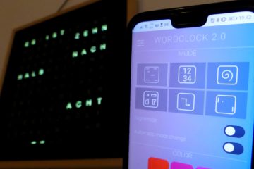
Hey folks! If you got a kick out of my Word Clock 2.0 build, you’re going to enjoy what’s up next. I’ve been tinkering away and am stoked to introduce the LED-RingClock. It’s another little project that combines the cool glow of NeoPixel LEDs with the brains of an ESP8266 microcontroller. I’m hoping it’ll catch your interest just like the Word Clock did, and maybe even present a fun challenge for those of you who loved putting that together.
This time around, we’re going to dive into making a RingClock that stands out with its vibrant colors and dynamic patterns, all thanks to the NeoPixel LEDs. Whether you’re here to build on what you know or just looking for something new to try, this project is bound to be a rewarding journey into DIY electronics. So, let’s grab our soldering gear, an ESP8266, and a strand of NeoPixels, and get set to put together another cool timepiece that’ll surely spark some conversations in your tech circles.


Features of the clock:
- receives time updates via a NTP server
- automatic switches between summer and winter time
- provides easy WIFI setup with WifiManager
- has a HTML webserver interface for configuration and control
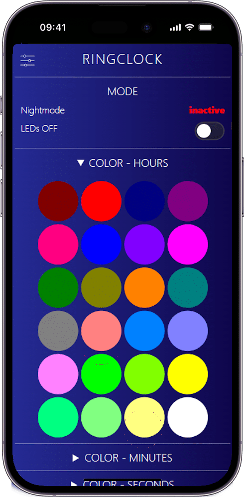
- color of display is configurable
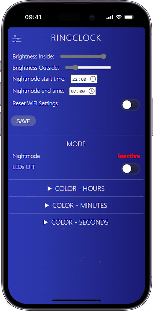
- night mode is configurable (start and end time)
- brightness of LEDs is adjustable
- an automatic current limiting of LEDs protects the power supply
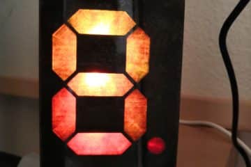
Variants of the clock:
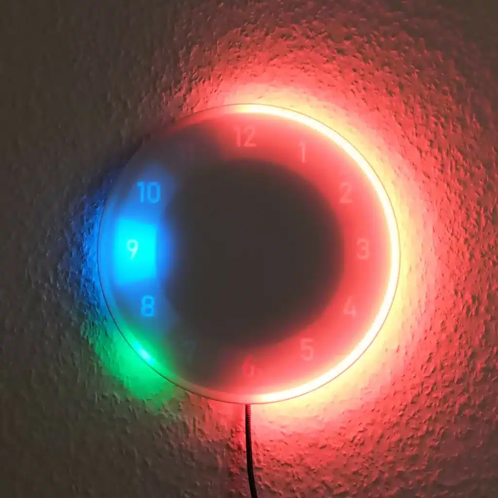
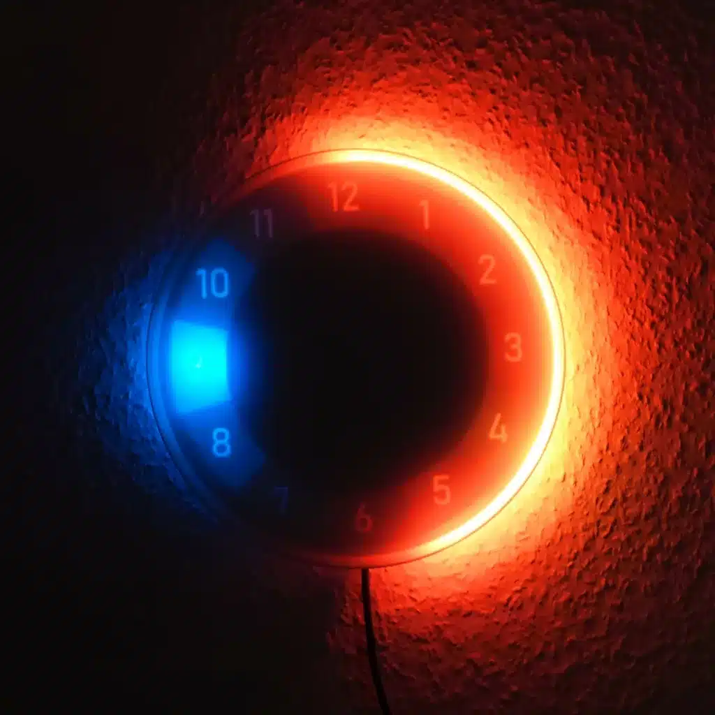
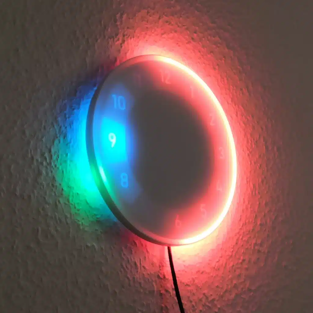
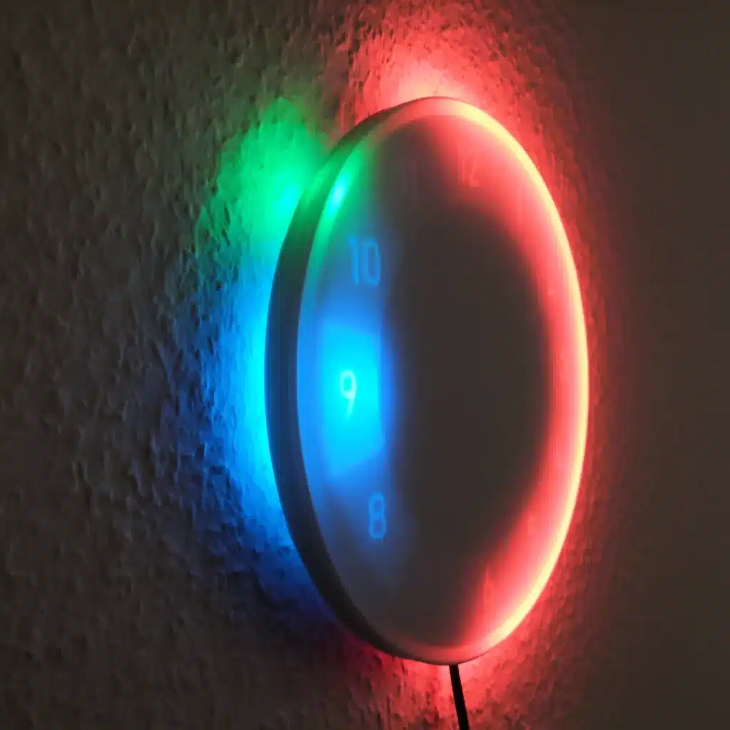
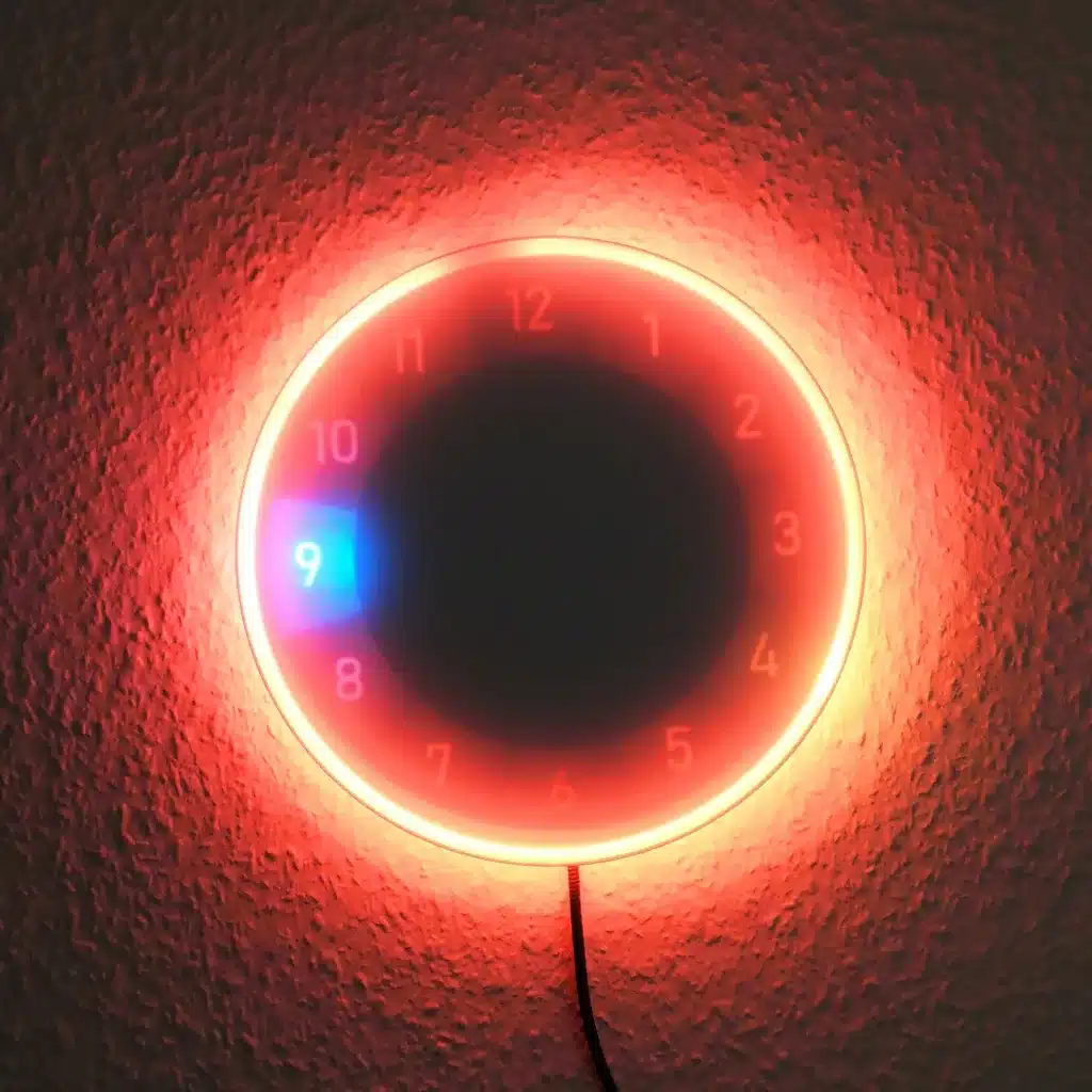
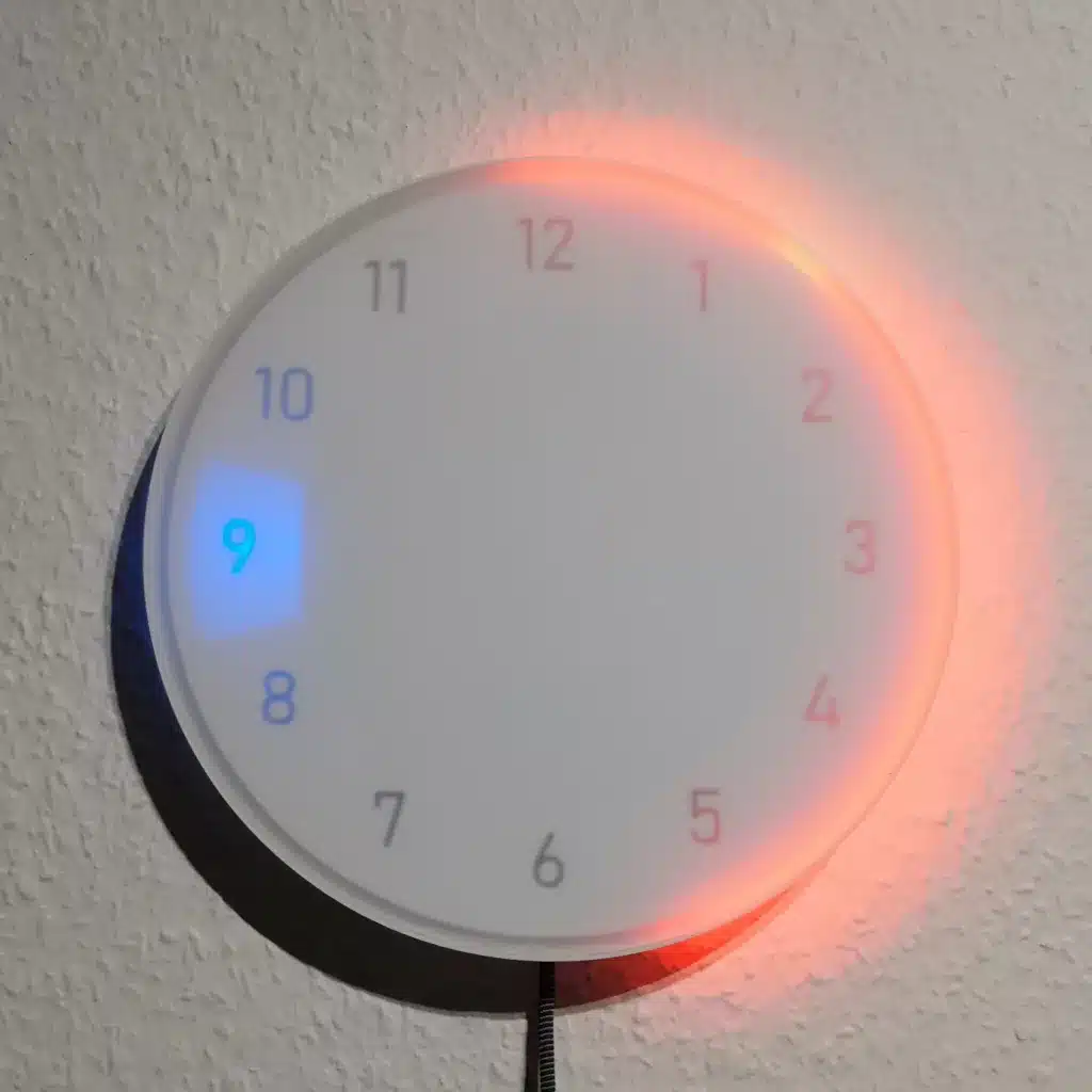
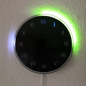
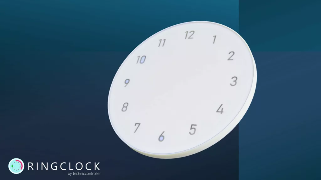
I have built two versions of the clock. One with a white dial and one with a black dial. I also used Roman numerals on one and Arabic numerals on the other. In this post, I will mainly show the process using the variant with the white dial and only refer to relevant changes for the black variant.
Content
- Material for the RingClock
- Building the Hardware
- 1. STEP: Drawing the front panel foil
- 2. STEP: Sticking the front panel foil on the acrylic plate
- 3. STEP: Preparing the back panel
- 4. STEP: Printing and preparing the central grid structure and outer ring
- 5. STEP: Mounting the electronic components
- 6. STEP: Assembling the RingClock
- The Software
- User Manual for the RingClock
1. Material for the RingClock with NeoPixel and ESP8266
You need the following material for building this clock:
- NeoPixel-Strip with 91x WS2812b LEDs (144 LEDs/m) (amazon.de*),
- NeoPixel-Strip with 12x WS2812b LEDs (30 LEDs/m) (amazon.de*),
- D1 Mini ESP8266 (amazon.de*),
- USB power supply 5V/3A (amazon.de*),
- Acrylic glass panel (color: opal white, thickness: 3mm, diameter 200 mm) (kunstoffplattenonline.de),
- Acrylic glass panel (color: frost opal white, thickness: 3mm, diameter 220 mm) (kunstoffplattenonline.de),
- white foil plot adhesive film with cut-out numbers for the clock face (printingpoint.de),
- black adhesive film (for variant with black dial, the roman numbers can be cut with knife),
- 2x 470 Ohm resistor,
- 1000uF capacitor,
- USB-C breakout socket (ebay.de),
- micro USB breakout plug (ebay.de),
- USB-C cable (amazon.de*),
- 4x Countersunk Head Screw M3x16
- 4x M3 Thread Insert (amazon.de*)
- 4x Nut M4 (no typo, we use the nut just as a spacer)
- some cables
Additionally, some special tools are needed:
- soldering iron
- spray bottle
- hot glue
- cutter knife
- 3D-Printer (see FAQ if you have no 3D printer)
* The links are affiliate links. The offers do not come from me, however, I receive a commission through the reference, if then a purchase takes place, but without you incurring additional costs.
2. Building the Hardware
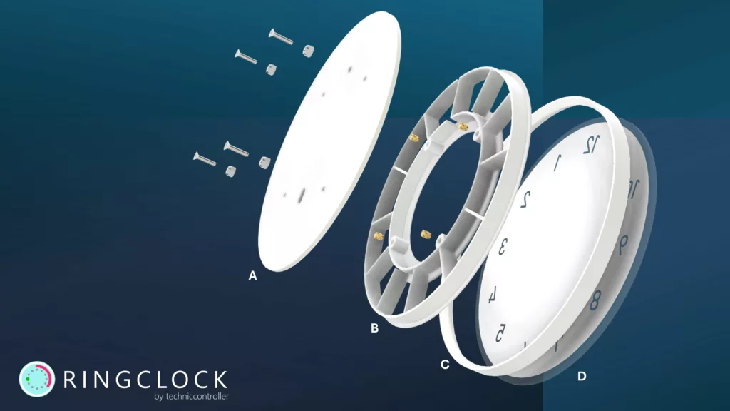
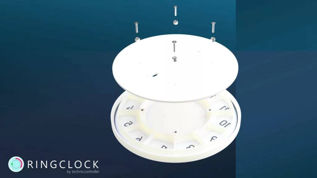
The clock consists of a total of four parts. The four parts are shown in an exploded view in the following picture.
- A: back panel with several holes for cable entry and fastening
- B: 3D printed central grid structure
- C: 3D printed outer ring cover
- D: front panel with the glued-on clock face
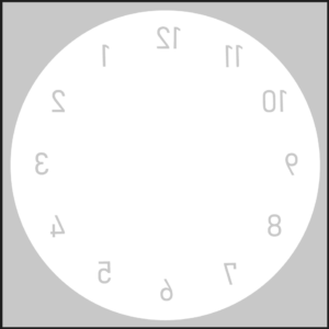
STEP 1: Drawing the front panel foil
I decided to have the foil for the front panel already professionally pre-cut instead of cutting out each letter individually from the foil with a knife by myself. To order the pre-cut foil you need a vector graphic of the foil. This can be done best with the free program Inkscape.
You can download the vector graphic file template as well as the print-ready file from the GitHub repository.
Black dial: For the black dial I used roman numbers, which I can cut manually with a knife out of black adhesive foil. The template file for roman numbers is also available in the GitHub repository.
STEP 2: Sticking the front panel foil on the acrylic plate
The front panel foil needs to be stuck on the larger of the two acrylic plates. Sticking the foil onto the glass plate is a bit tricky. But with the following tips it worked well for me:
- Clean the work surface thoroughly.
- Remove the protection film from the acrylic plate.
- Spray hands with a water-soap mixture (1L water + 1 spoon of dish soap).
- Remove the protective film from the adhesive foil.
- Wet the acrylic plate and the foil with the mixture of water and dish soap from a spray bottle.
- Place the foil on the acrylic and using a squeegee with a felt edge, carefully brush all air bubbles from the center to the edge (5-10 minutes).
- You can remove the transfer paper after a drying time of 10-12 hours.
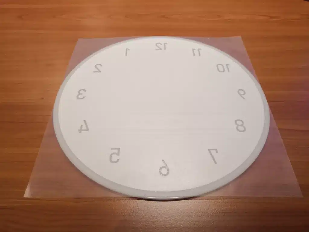
Black dial: Unlike the white dial, the black dial has to be glued to the front of the front panel. For this reason, I did not cut the numbers out of the black adhesive film the wrong way round (mirrored).
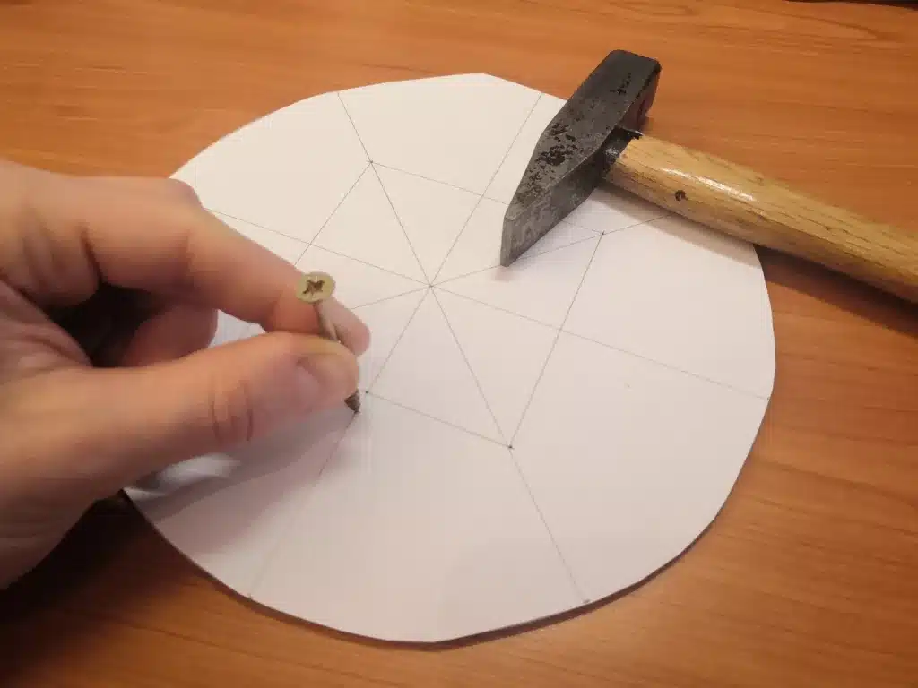
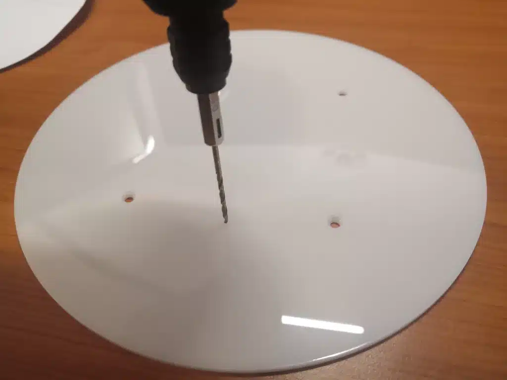
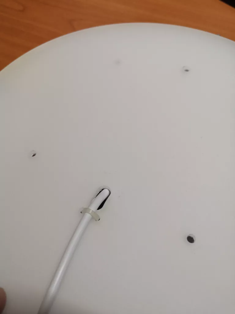
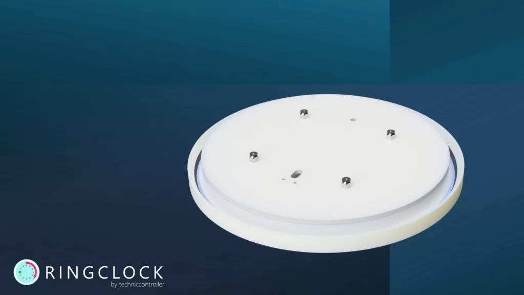
STEP 3: Preparing the back panel
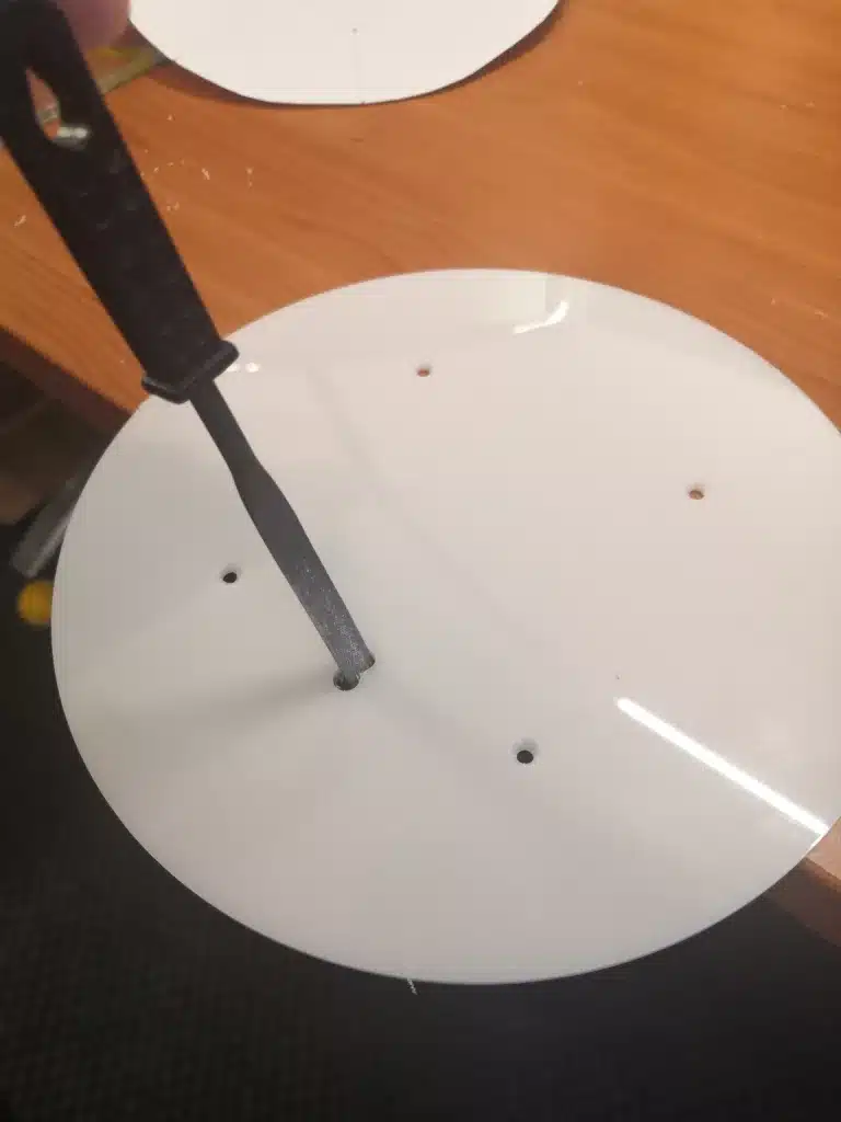
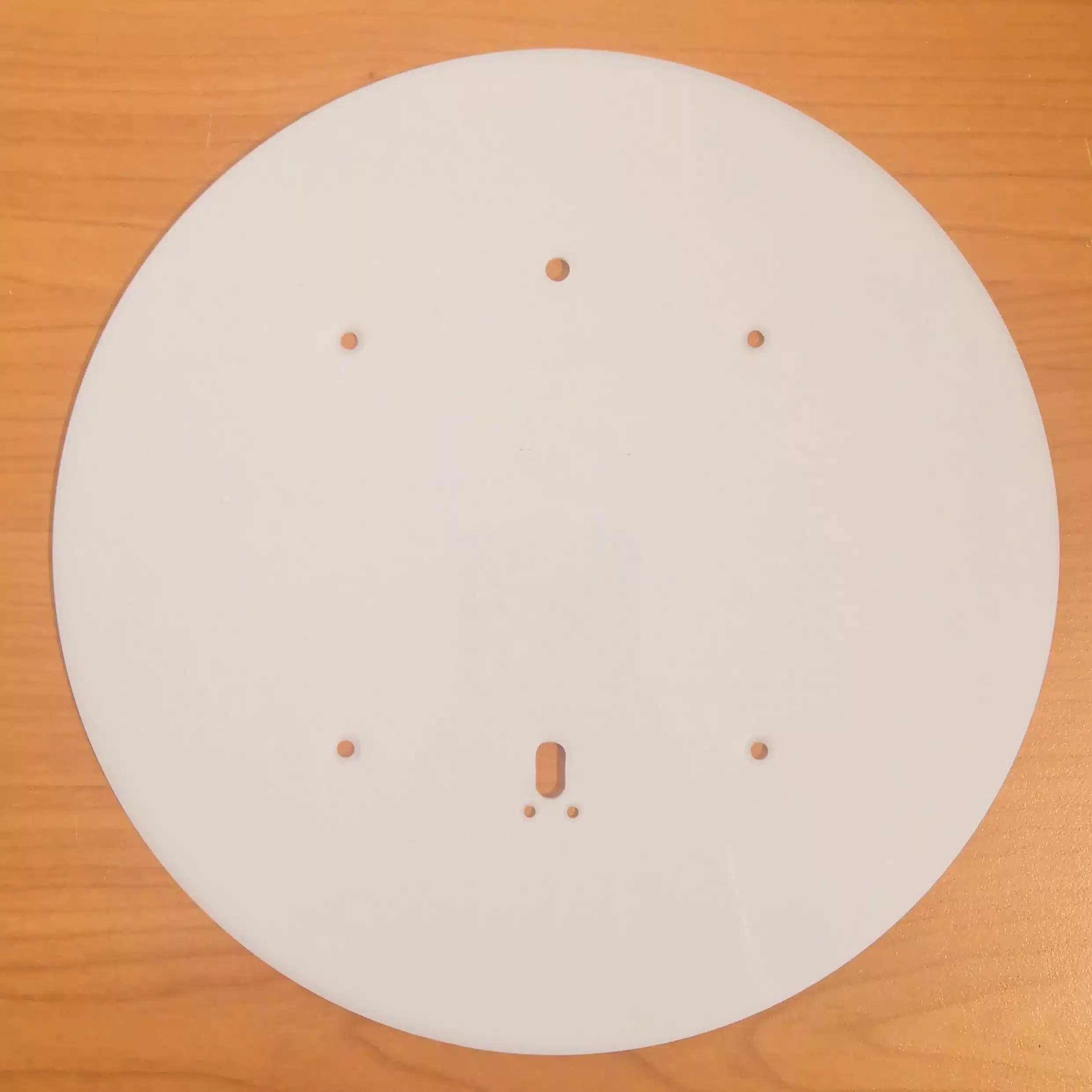
We need to drill some holes in the back panel. To simplify the positioning, I have created a template that shows the position of all the holes. You can simply print out the template and transfer the position of the holes to the acrylic plate using a nail or screw, as shown in the photos. You can then drill the holes with a drill. The slotted hole must be created for the USB cable. To do this, it helps to first drill two holes and then use a file to connect the two holes to form a slotted hole.
STEP 4: Printing and preparing the central grid structure and outer ring
As the central structure is quite complicated, I decided to print it with my 3D printer from white PLA filament. I have uploaded the STL file and the original CAD file to my GitHub, so you just need to download it and print it with a 3D printer. Use the following printing settings:
- Material: White PLA
- Layer Height: 0.2 mm
- Infill: 50%
- Support: None
As the part is quite large and does not have much surface to lay on the build plate, it will likely suffer from warping. I would therefore recommend printing it with a brim in the Build Plate Adhesion settings.
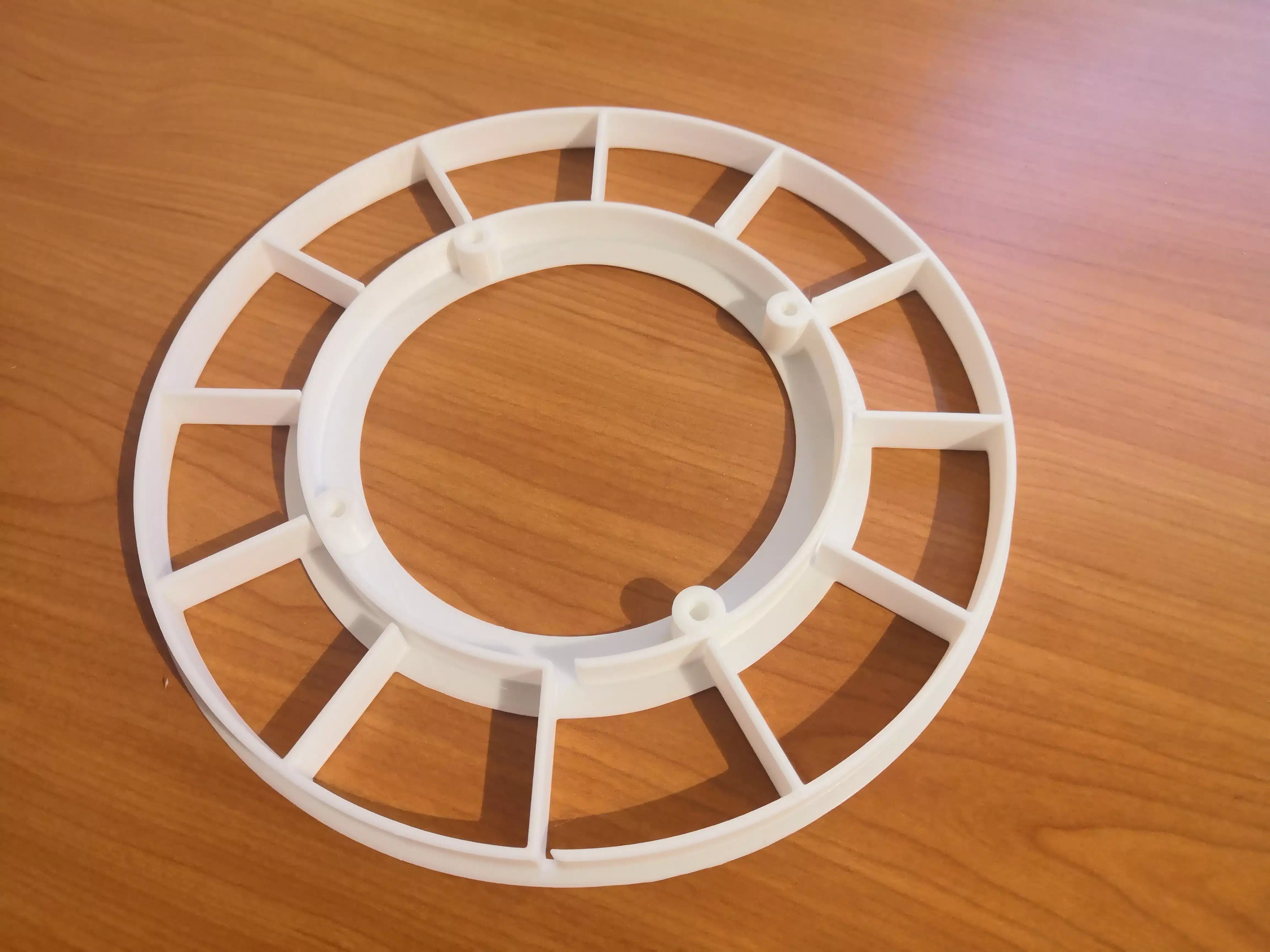
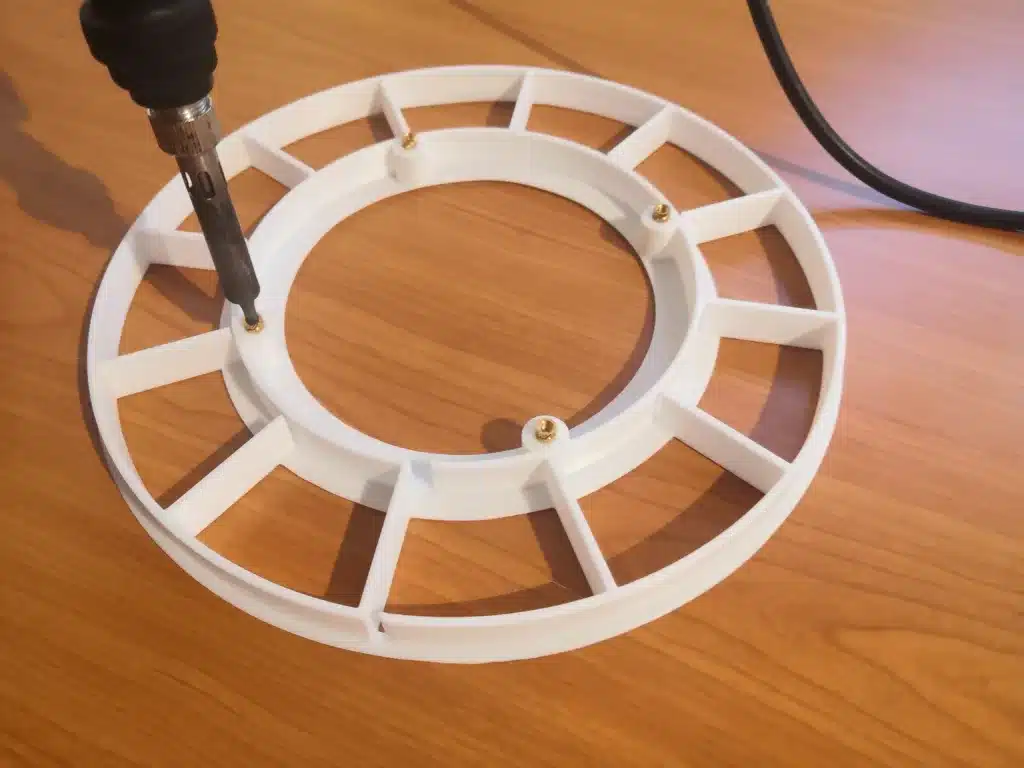
After printing the central grid structure, the thread inserts still have to be melted into the holes using a soldering iron, as can be seen in the following picture.
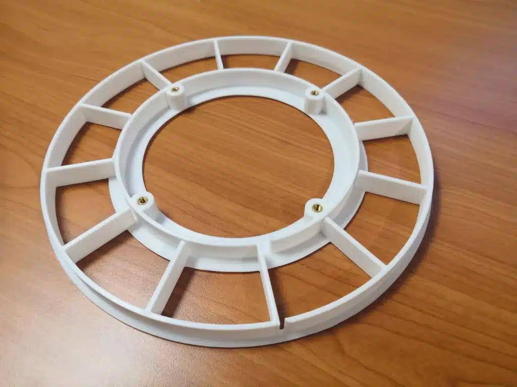
The outer ring is also printed with the same settings as the central grid structure.
STEP 5: Mounting the electronic components
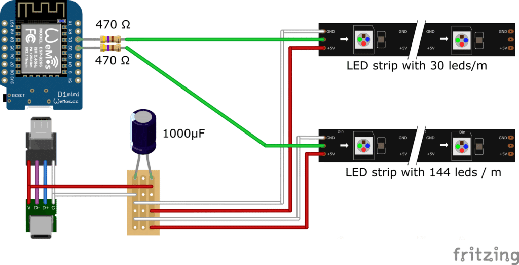
The wiring of the components is not complicated. The wiring diagram is shown here.
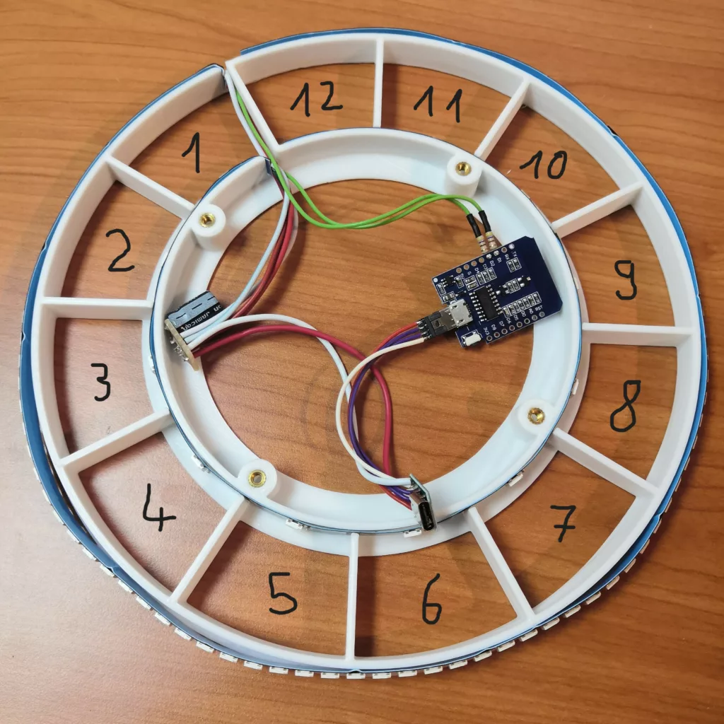
To assemble the electronics you can follow these steps:
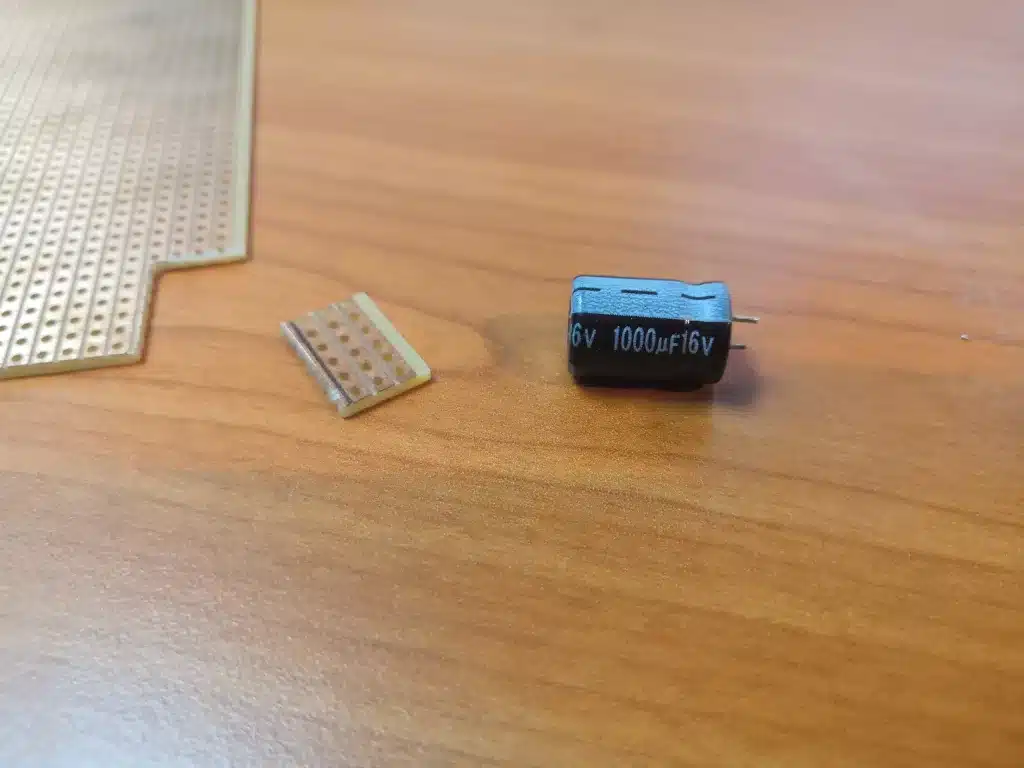
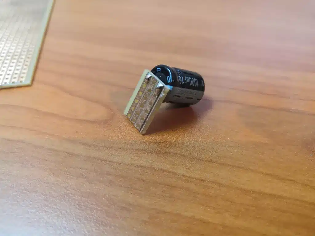
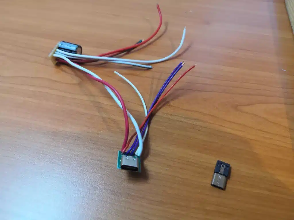
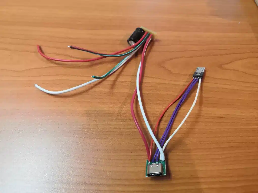
- Start by preparing a compact breadboard, which will act as the central power hub for the project. Solder the capacitor onto the board along with three pairs of wires, with each pair comprising one red and one white wire. This setup will be powered with a 5V input from the USB-C breakout board and will distribute power to the two LED strips. Attach one pair of the red and white wires to the USB-C breakout board, ensuring the red wire connects to the “V” (voltage) terminal and the white wire to the “G” (ground) terminal. (Picture 1, 2, 3)
- Align the breakout boards and connect all four terminals of the USB-C breakout board directly to their corresponding counterparts on the micro-USB breakout board. This crucial step provides the necessary power to the ESP8266 module. (Picture 4)
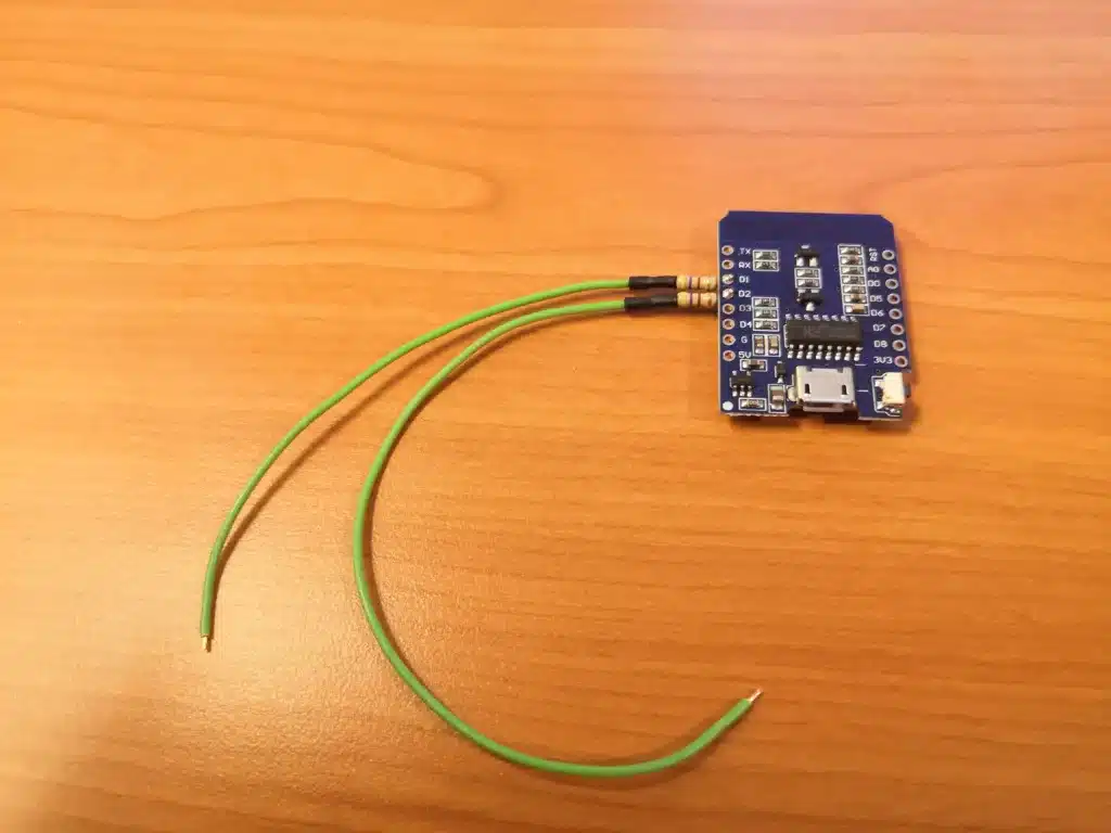
- Proceed by soldering each of the two resistors to a separate green wire. Then, connect the resistors to the D1 and D2 pins on the ESP8266. These connections will act as the signal lines for the LED strips. (Picture 5)
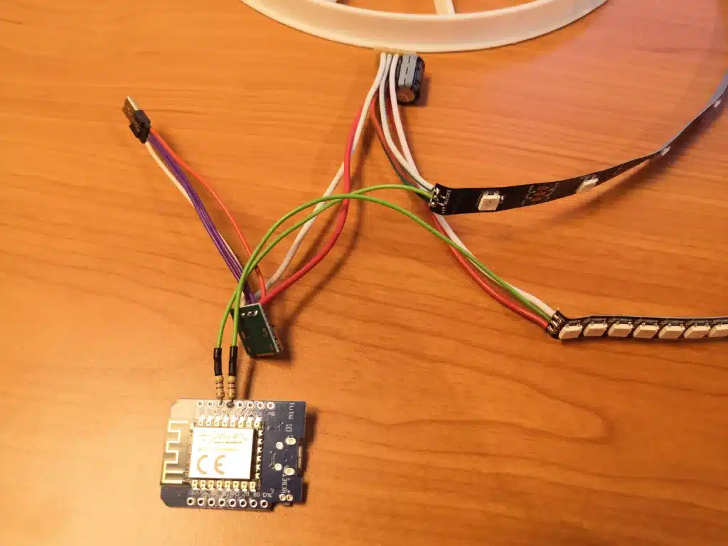
- Complete the assembly by attaching the LED strips. Connect each strip to the red and white wires from the power supply breadboard, ensuring the red wire links to the 5V terminal and the white wire to the GND (ground) terminal on each strip. The green wire should be connected to the “DI” (data input) terminal on the LED strips. This step finalizes the LED strips’ power and signal pathways, ensuring they operate as intended. (Picture 6)
Pictures of the individual steps are shown below.
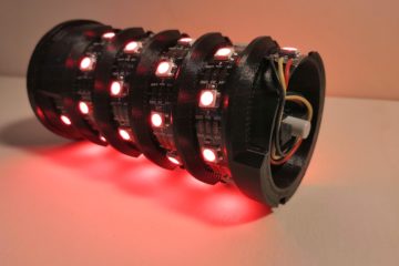
STEP 6: Assembling the RingClock
After connecting all the electronic components, you can proceed to assemble the RingClock. Position the LED strip featuring densely packed LEDs around the outer perimeter of the central grid structure. Then, place the LED strip with 12 LEDs along the inner circle of the central grid. Utilize the adhesive backing on the LED strips to securely affix them to the corresponding sections of the 3D-printed component.
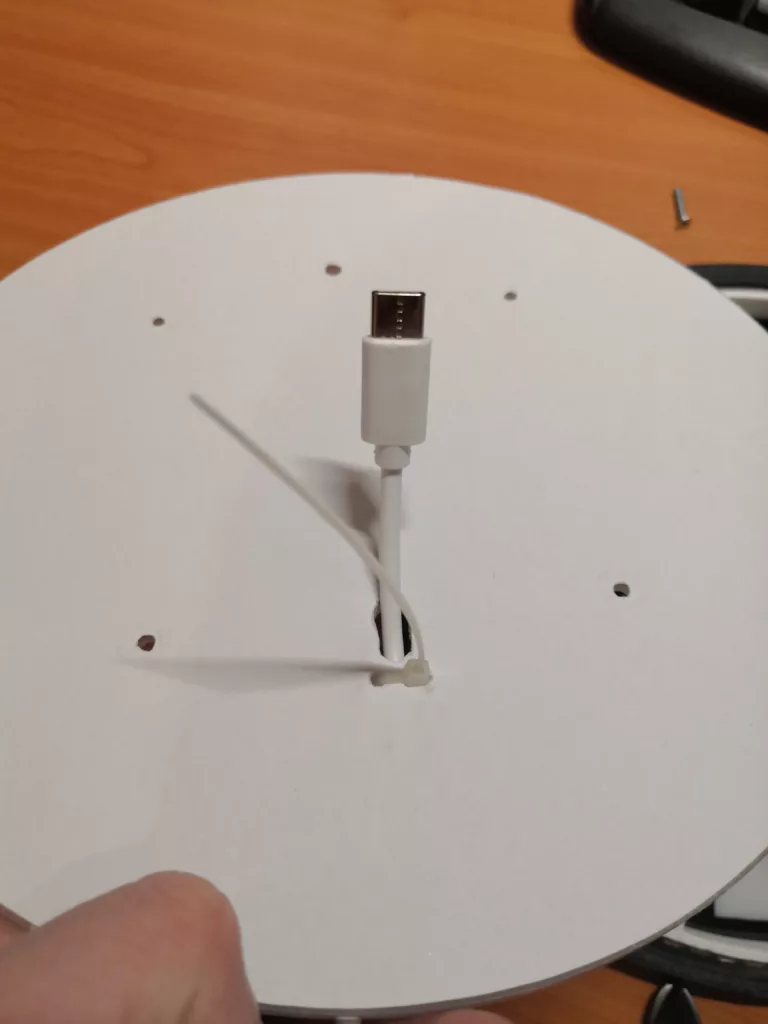
Guide one side of the USB-C cable through the slotted hole in the back panel and, ideally, secure the cable with a cable tie. Use the two small holes near the slotted hole as shown in the photo.
Now glue the central grid structure to the front panel using superglue. Make sure that the first LED of the inner LED strip illuminates the number 1. Once the glue has dried, the back panel can be mounted using the four screws. I use the four large nuts as spacers to the wall so that the cable can be routed out of the tube without any problems.
As a final step, the outer ring can now be glued to the front panel with superglue.
3. The Software
Quickstart
For those who want to get started directly with the code, you can find the complete source code on GitHub:
techniccontroller / ringclock_esp8266
ESP8266 source code for RingClock on GitHub
- Just clone the project into the sketch folder of the Arduino IDE,
- Install the additional libraries and flash it to the ESP8266 as usual.
- The implemented WiFiManager helps you to set up a WiFi connection with your home WiFi -> on the first startup it will create a WiFi access point named “RingclockAP”. Connect your phone to this access point and follow the steps shown to you.
- After a successful WiFi setup, open the browser and enter the IP address of your ESP8266 to access the interface of the web server.
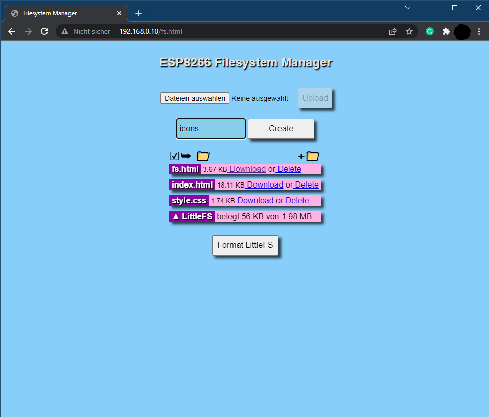
- Here, you can upload all files, that are located in the folder “data”. Please make sure all icons stay in the folder “icons”.
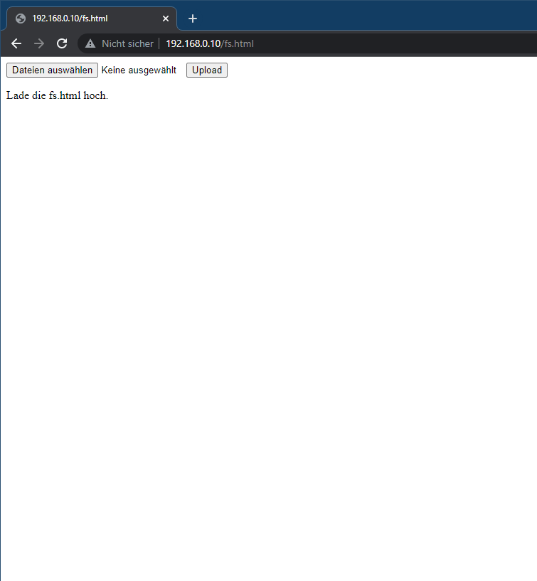
- Open http://<ip-address>/fs.html in a browser
- Upload fs.html
- Upload style.css
- Upload index.html
- Create a new folder icons
- Upload all icons into this new folder icons
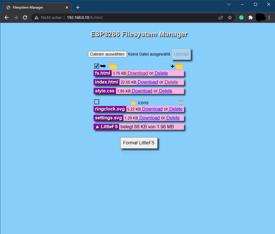
The RingClock is now ready. Navigate to http://<ipaddress>/ or http://ringclock.local/ to open the web server interface of the RingClock and have fun with it!
Detailed Look
For anyone interested in delving deeper into the software’s internals, I’d like to offer a more detailed explanation here. Those familiar with my Word Clock 2.0 article might recognize a significant overlap between the source codes of these two projects. I’ve repurposed substantial portions of the Word Clock 2.0 code for the RingClock software, maintaining a consistent software architecture. The diagram below outlines the software’s structure, highlighting both third-party and my own libraries. Additionally, to streamline the code, I’ve outsourced certain functionalities into distinct .ino files.
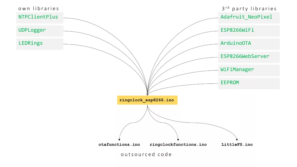
OWN LIBRARIES
NTPClientPlus
This library handles all the NTP update stuff, like getting a new time update, converting it to the correct timezone, calculating summer- or wintertime, and splitting the time up in hours, minutes and seconds.
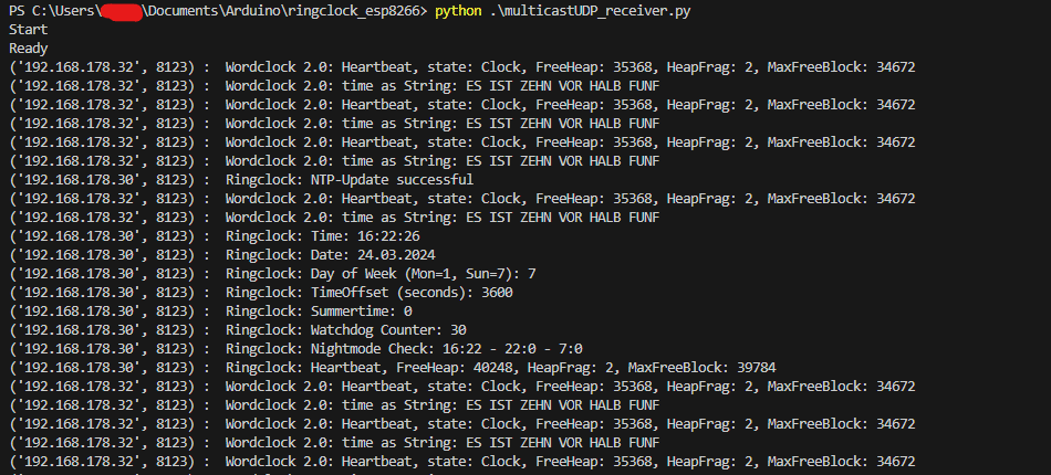
UDPLogger
As the ESP8266 is most of the time not connected to a computer, it would be convenient to still have some information about what the controller is currently doing. I created this library already for previous projects. With this library, you can easily send UDP multicast messages into the network and everyone in the network can receive these messages. I wrote a small python script (multicastUDP_receiver.py) that can receive and display the messages.
LEDRings
This library encompasses all functions necessary for controlling the LEDs on both rings, including those for initialization, individual pixel manipulation, and brightness adjustment.
Mirroring the approach of the LEDMatrix library from Wordclock 2.0, it integrates a low-pass filter to ensure fluid transitions between various LED patterns displayed on the rings. The mechanism behind this involves a straightforward algorithm, where the color value of a pixel to be displayed is determined through a specific calculation, ensuring a smooth visual effect
factor = [0...1]
filteredValue_R = currentValue_R + factor * (newValue_R - currentValue_R)
filteredValue_G = currentValue_G + factor * (newValue_G - currentValue_G)
filteredValue_B = currentValue_B + factor * (newValue_B - currentValue_B)
I have also implemented the LED current limiting and automatic dimming function in this class. Before writing the color values to the LED strip, the code estimates the total current that is needed to display the given pattern. If the estimated current is above the configurable current limit, it will automatically reduce the overall brightness to meet the total current limit. The code snippet is shown below:
/**
 * @brief Calc estimated current (mA) for one pixel with the given color and brightness
 *
 * @param color 24bit color value of the pixel for which the current should be calculated
 * @param brightness brightness value (0-255)
 * @return the current in mA
 */
uint16_t LEDRings::calcEstimatedLEDCurrent(uint32_t color, uint8_t brightness){
  // extract rgb values
  uint8_t red = color >> 16 & 0xff;
  uint8_t green = color >> 8 & 0xff;
  uint8_t blue = color & 0xff;

  // Linear estimation: 20mA for full brightness per LED
  // (calculation avoids float numbers)
  uint32_t estimatedCurrent = (20 * red) + (20 * green) + (20 * blue);
  estimatedCurrent /= 255;
  estimatedCurrent = (estimatedCurrent * brightness)/255;

  return estimatedCurrent;
}

/**
 * @brief Draw the target color on the rings
 *
 * @param factor transition factor (1.0 = instant, 0.1 = smooth)
 */
void LEDRings::drawOnRings(float factor){
    // calculate current limit
    uint16_t currentLimitOuterRing = currentLimit / OUTER_RING_LED_COUNT;
    uint16_t currentLimitInnerRing = currentLimit / INNER_RING_LED_COUNT;

    // set pixels on outer ring and calculate current for outer ring
    uint16_t totalCurrentOuterRing = 0;
    for(int i=0; i<OUTER_RING_LED_COUNT; i++) {
        uint32_t currentColor = currentOuterRing[i];
        uint32_t targetColor = targetOuterring[i];
        uint32_t newColor = interpolateColor24bit(currentColor, targetColor, factor);
        int correctedPixel = (OUTER_RING_LED_COUNT + i + offsetOuterRing) % OUTER_RING_LED_COUNT;
        outerRing->setPixelColor(correctedPixel, newColor);
        currentOuterRing[i] = newColor;

        totalCurrentOuterRing += calcEstimatedLEDCurrent(newColor, brightnessOuterRing);
    }

    // set pixels on inner ring and calculate current for inner ring
    uint16_t totalCurrentInnerRing = 0;
    for(int i=0; i<INNER_RING_LED_COUNT; i++) {
        uint32_t currentColor = currentInnerRing[i];
        uint32_t targetColor = targetInnerRing[i];
        uint32_t newColor = interpolateColor24bit(currentColor, targetColor, factor);
        int correctedPixel = (INNER_RING_LED_COUNT + i + offsetInnerRing) % INNER_RING_LED_COUNT;
        innerRing->setPixelColor(correctedPixel, newColor);
        currentInnerRing[i] = newColor;

        totalCurrentInnerRing += calcEstimatedLEDCurrent(newColor, brightnessInnerRing);
    }

    uint16_t totalCurrent = totalCurrentOuterRing + totalCurrentInnerRing;

    // Check if totalCurrent reaches CURRENTLIMIT -> if yes reduce brightness
    if(totalCurrent > currentLimit){
        uint8_t newBrightnessOR = brightnessOuterRing * float(currentLimit)/float(totalCurrent);
        uint8_t newBrightnessIR = brightnessInnerRing * float(currentLimit)/float(totalCurrent);
        //logger->logString("CurrentLimit reached!!!: " + String(totalCurrent));
        outerRing->setBrightness(newBrightnessOR);
        innerRing->setBrightness(newBrightnessIR);
    }
    else {
        outerRing->setBrightness(brightnessOuterRing);
        innerRing->setBrightness(brightnessInnerRing);
    }

    // show rings
    outerRing->show();
    innerRing->show();
}
OUTSOURCED CODE
otafunctions.ino
This file includes all the essential functions required for configuring ArduinoOTA updates. It comprises mainly two functions: setupOTA() and handleOTA(). The objective is to streamline the process by relocating this standard code away from the main file, ensuring simplicity and efficiency.
LittleFS.ino
This file is an unchanged takeover from https://fipsok.de/Esp8266-Webserver/esp8266. It provides a very nice file manager for the easier upload of files to ESP8266.
ringclockfunctions.ino
This file houses the functions responsible for displaying the hours and minutes on the LED rings. Specifically, the showHour() and showMinutes() functions translate time values into the appropriate illumination of LEDs on the rings.
void showTimeOnClock(uint8_t hour, uint8_t minutes, uint32_t colorHours, uint32_t colorMinutes, uint32_t colorSeconds) {
    showHour(hour, colorHours);
    showMinutes(minutes, colorMinutes, colorSeconds);
}
4. User Manual for the RingClock
To complement your RingClock journey, I’ve prepared an extensive user manual tailored for the end user, detailing the operation and functionalities of the RingClock. Available as a PDF download, this guide offers a thorough walkthrough to help you make the most of your RingClock experience.
Have fun rebuilding it! If you have any questions, please feel free to write a comment.
4 Comments
Andre · 09/07/2024 at 19:25
A wonderful clock! I’ve completed several clock projects so far, including Edgar’s Word-Clock 2.0 (a real eye-catcher, and I’ve received many compliments for it). Edgar’s RingClock is equally fascinating. The sketch is perfect and error-free. And if something still doesn’t work, you can email Edgar and receive prompt and competent support. Both are not taken for granted, and I truly appreciate both. Thank you very much, Edgar, for your work and for sharing this project. I highly recommend building it.
Techniccontroller · 09/07/2024 at 20:41
Hi Andre,
thank you very much for your comment and the very nice words. I am happy that you like my clock projects.
Best regards
Edgar
Zsolt · 12/04/2024 at 16:34
Hi, Great job but stl file not found on Github please sen me? Thanks
Techniccontroller · 12/04/2024 at 20:36
Hello Zsolt,
thank you for you comment.
Oh, you are right, I forgot to upload the STL files.
The STL files are now on GitHub.
Best regards
Edgar