Two years ago I already built a word clock with NeoPixel LEDs. You can find the article about it here. At that time I built the word clock only with an Arduino and queried the time via radio. But this time the plan is to make the clock bigger, prettier and with more features. The word clock with WiFi gets the time from an NTP server and can control some functions via an HTML webserver on the microcontroller (ESP8266). Here is a quick overview of all features before I get into the step-by-step instructions.
Features of the clock:
- has 6 modes (Clock, Digital Clock, SPIRAL animation, TETRIS, SNAKE, PONG)
- receives time updates via a NTP server
- automatic switches between summer and winter time
- provides easy WIFI setup with WifiManager
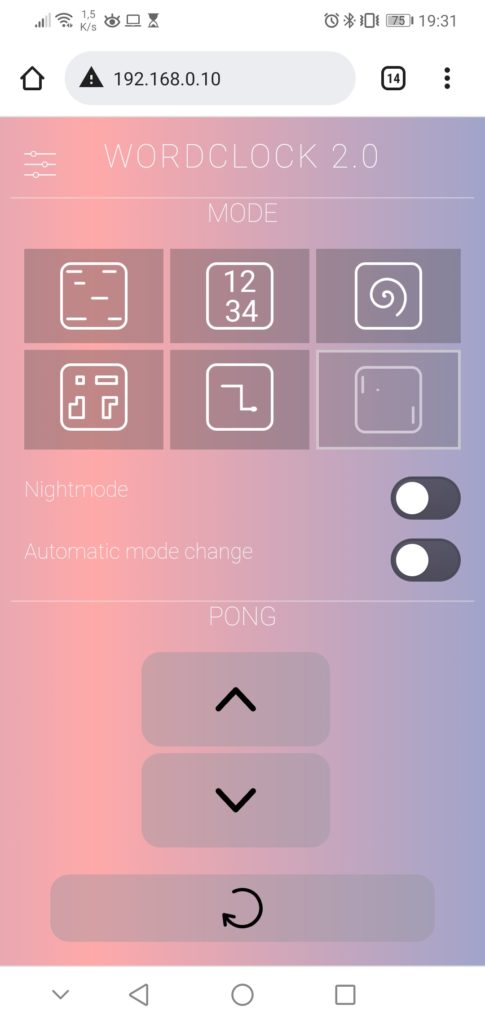
- has a HTML webserver interface for configuration and control
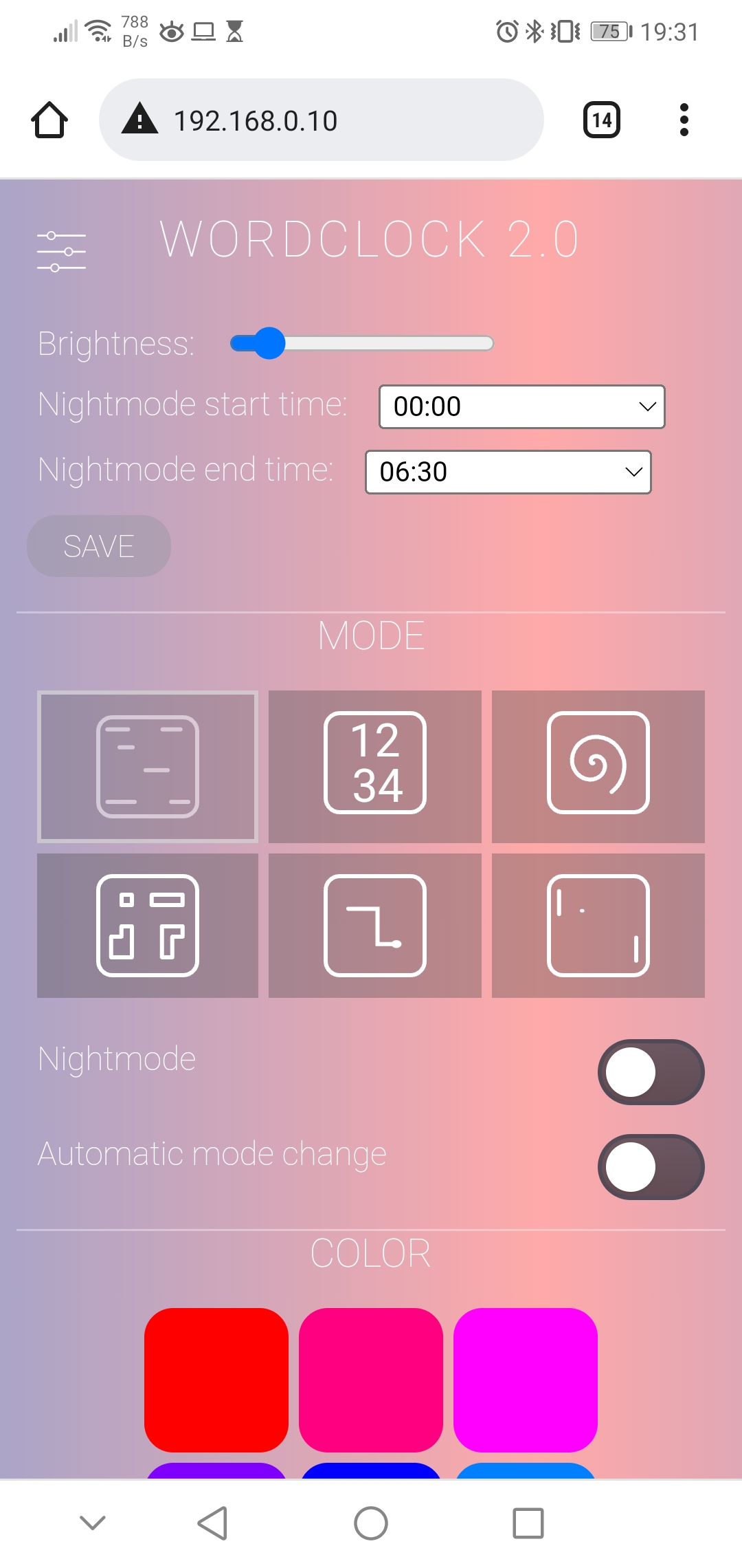
- color of display is configurable
- night mode is configurable (start and end time)
- brightness of LEDs is adjustable
- automatic mode change every 10 seconds (optional)
- has a physical button to change mode or enable night mode without webserver
- an automatic current limiting of LEDs protects the power supply
Languages:
I provide the source code and front plate layout for German, English and Italian. See detailed instructions in the FAQ section below.
Content
- Material for the Word Clock with WiFi
- Step-by-Step Instructions: The Hardware
- 1. STEP: Drawing the front panel foil
- 2. STEP: Sticking the front panel foil on the glass plate
- 3. STEP: Cut and build the light grid
- 4. STEP: Mounting the electronics components
- 5. STEP: Bring everyting together
- Look at the Heart: The Software
1. Material for the Word Clock with WiFi
You need the following material for building this clock:
- wooden picture frame 50x50cm (about 2 cm deep),
- NeoPixel-Strip with 125x WS2812b LEDs (30 LEDs/m) (amazon.de*)
- ESP8266 NodeMCU V3 (amazon.de*),
- USB power supply 5V/3A (amazon.de*),
- cardboard 50x50cm,
- white backing paper,
- 470 Ohm resistor,
- 1000uF capacitor,
- push button (amazon.de*),
- micro USB socket (amazon.de*),
- micro USB cable (amazon.de*),
- some cables
Additionally, some special tools are needed:
- soldering iron
- spray bottle
- hot glue
- cutter knife
* The links are affiliate links. The offers do not come from me, however, I receive a commission through the reference, if then a purchase takes place, but without you incurring additional costs.
2. Step-by-Step Instructions: The Hardware
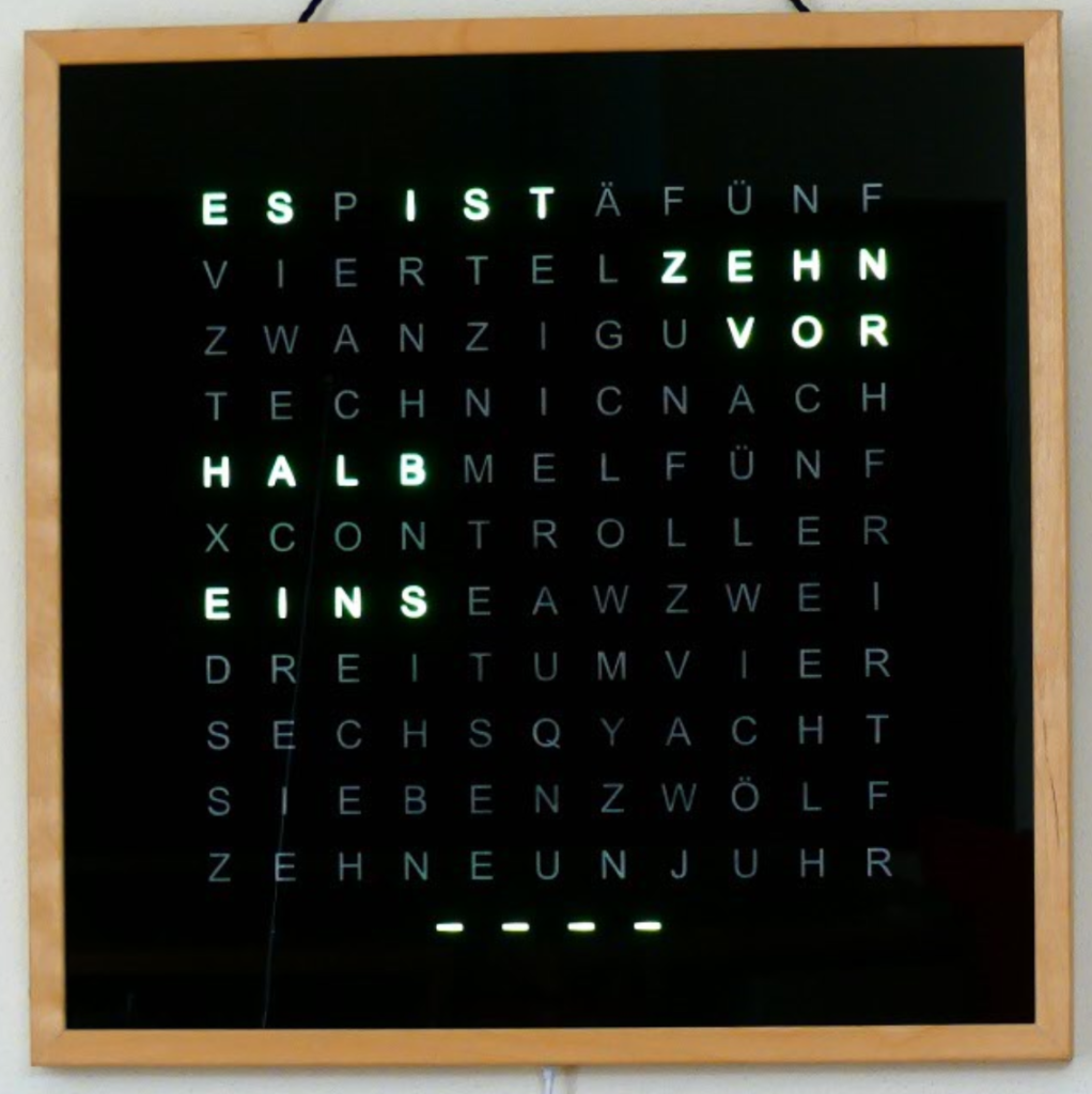
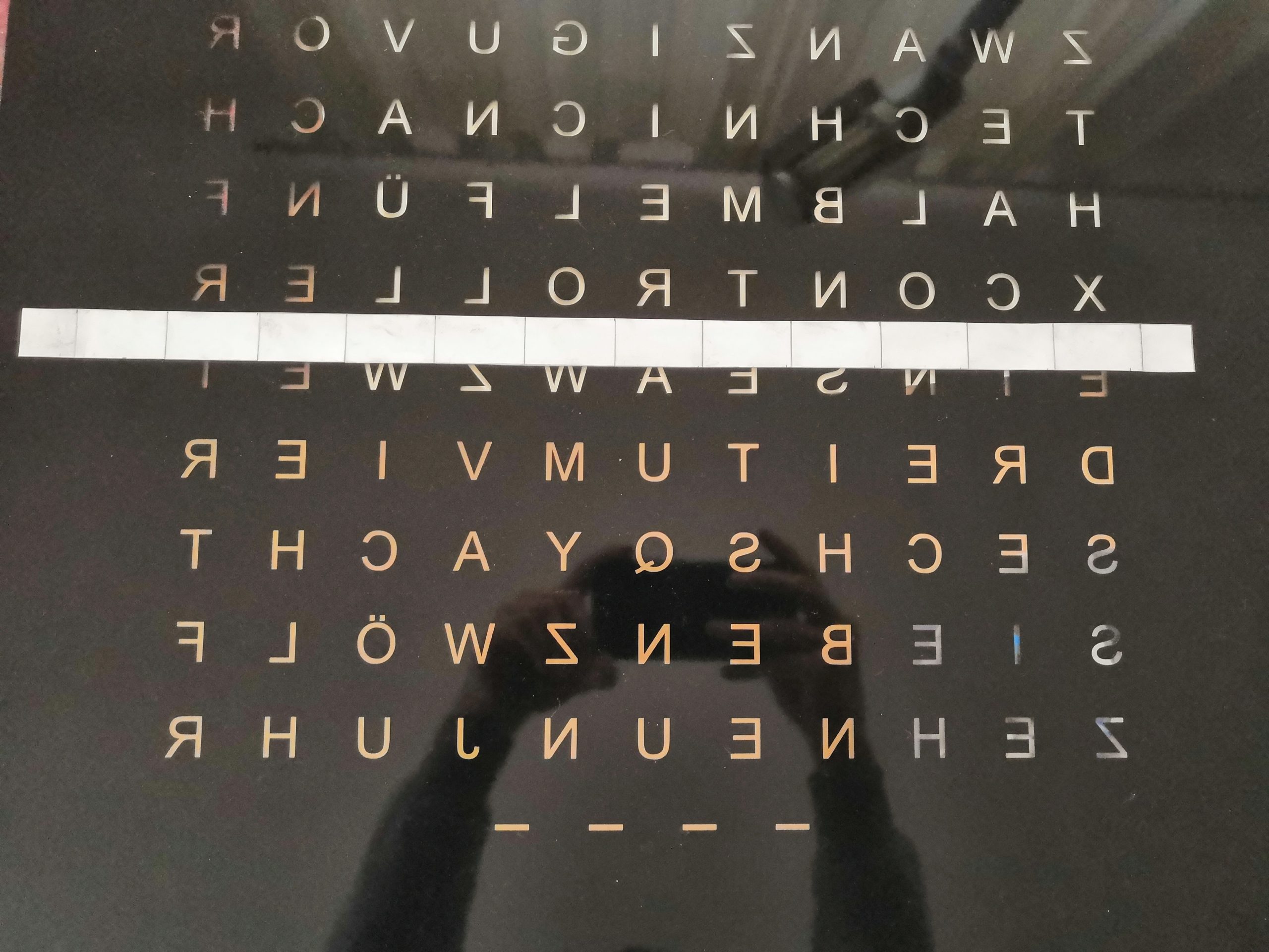
I will describe the build process of the hardware as step-by-step instructions as this will give you the best overview of the project. The mechanical base is again a particularly deep picture frame with a 500×500 mm glass plate. The distinguishing feature of the clock is of course the front panel, which this time contains 121 letters. That means it has eleven lines instead of only ten, which offers several advantages. On the one hand, it allows me to display my name “Techniccontroller”, on the other hand, it allows me to display two letters on top of each other. More details about this topic are in the chapter Digital clock.
STEP 1: Drawing the front panel foil
I decided to have the foil for the front panel lasered instead of cutting out each letter individually from the foil with a knife as I did with the first clock. To laser the foil you need a vector graphic of the foil. This can be done best with the free program Inkscape.
I have created a detailed How-To, in which I show how to draw the front plate with Inkscape:
You can also use my Inkscape template: Link to GitHub. The distance between the letters is 33.25 mm in both directions (horizontal and vertical) because I use a LED strip with 30 LEDs per meter.
STEP 2: Sticking the front panel foil on the glass plate
Sticking the foil onto the glass plate is a bit tricky. But with the following tips it worked well for me:
- Clean the work surface thoroughly.
- Clean the glass plate with glass cleaner.
- Spray hands with a water-soap mixture (1L water + 1 spoon of dish soap).
- Remove the protective film from the adhesive foil.
- Wet the glass plate and the foil with the mixture of water and dish soap from a spray bottle.
- Place the glass plate on the foil and using a squeegee with a felt edge, carefully brush all air bubbles from the center to the edge.
- Turn the glass plate over and spray transfer the paper side of the adhesive film with the water-soap mixture.
- Squeegee strongly and evenly from the inside out (5-10 minutes).
- You can remove the transfer paper after a drying time of 10-12 hours. Be careful to remove the paper from the top left to the bottom right at a flat angle so as not to damage the letters E and F.
Detailed instructions for sticking with a few additional pictures can be found here (german):
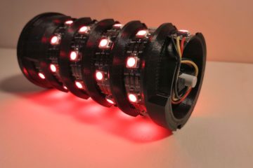
STEP 3: Cut and build the light grid
The light grid prevents the individual LEDs from shining into other letters. In addition, it serves as a reflector, which ensures uniform illumination of the individual letters. I use a little stronger cardboard, which I cut with scissors. Specifically, I cut 25 strips with the following dimensions:
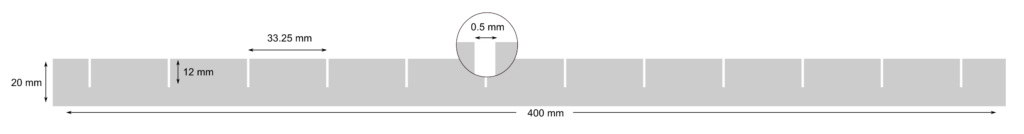
Then I put the strips together to form a grid structure and paint them with mirror paint. This helps to reflect the light from the LEDs better. Since the grid has bent a lot, I glued wooden rods on two sides to stiffen it.

When gluing the light grid to the back of the picture frame later, you may have to cut a few notches for the cables so that the light grid is flush with the back and prevents light leakage (see pictures below).
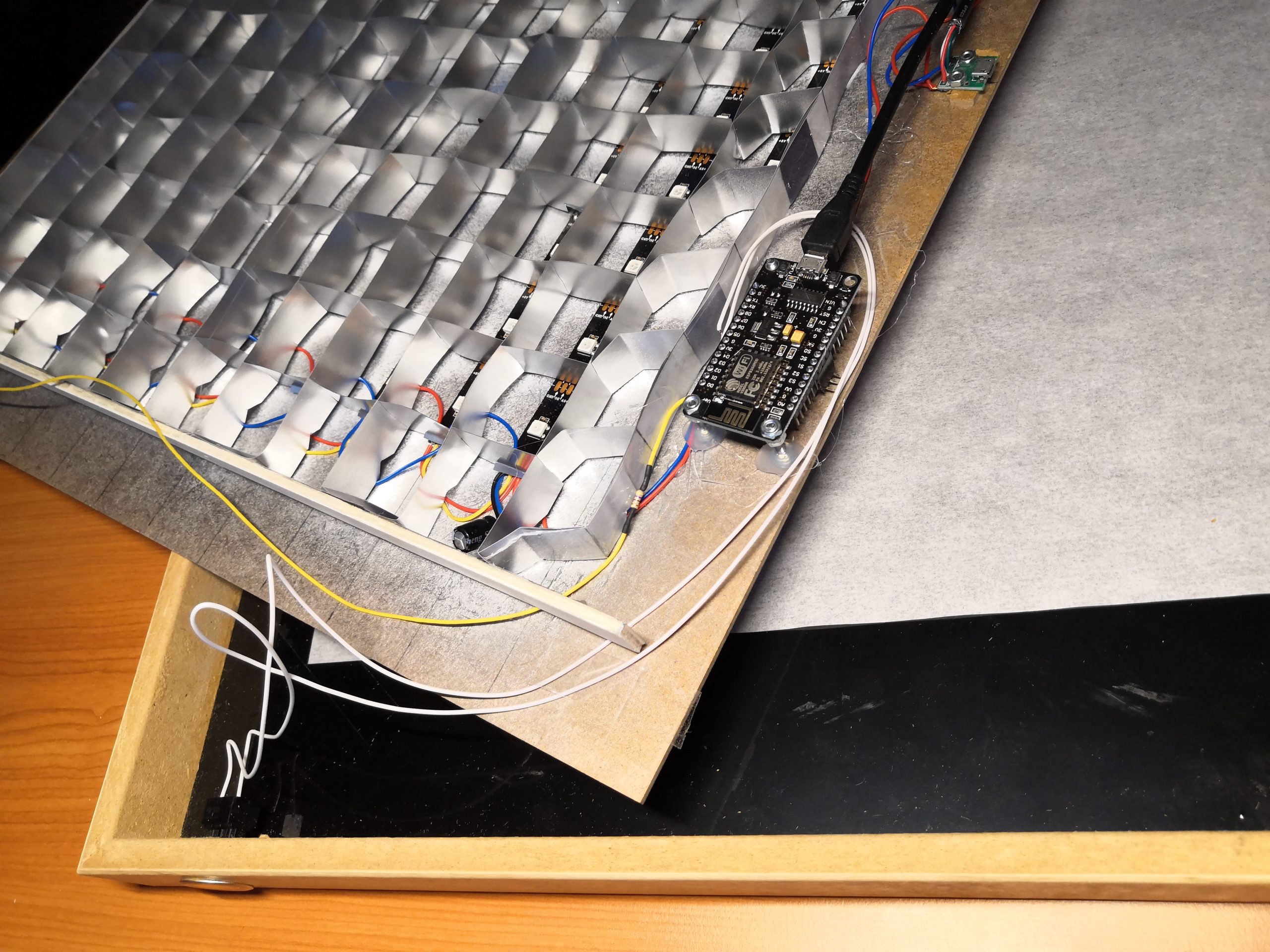
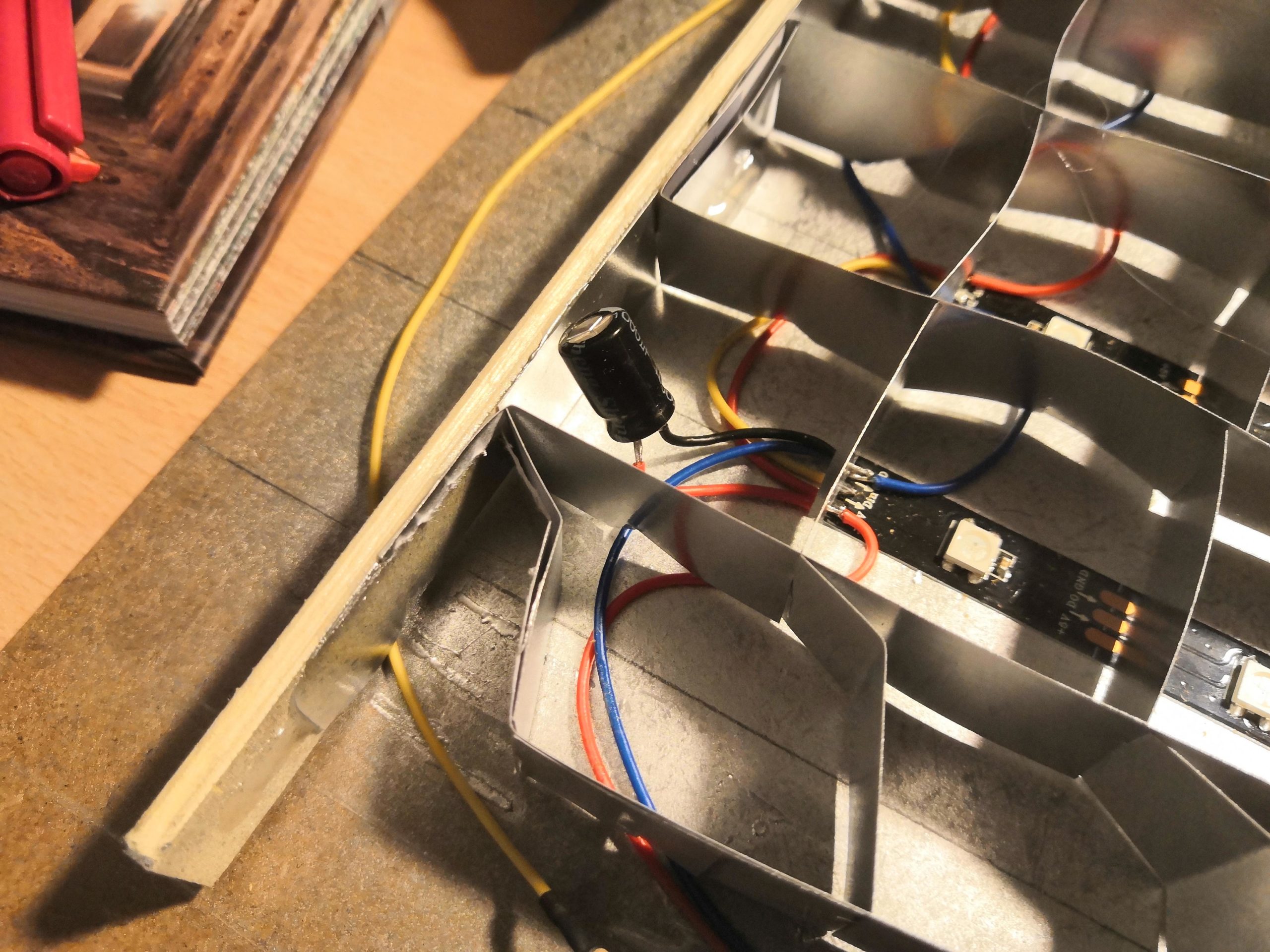
STEP 4: Mounting the electronic components
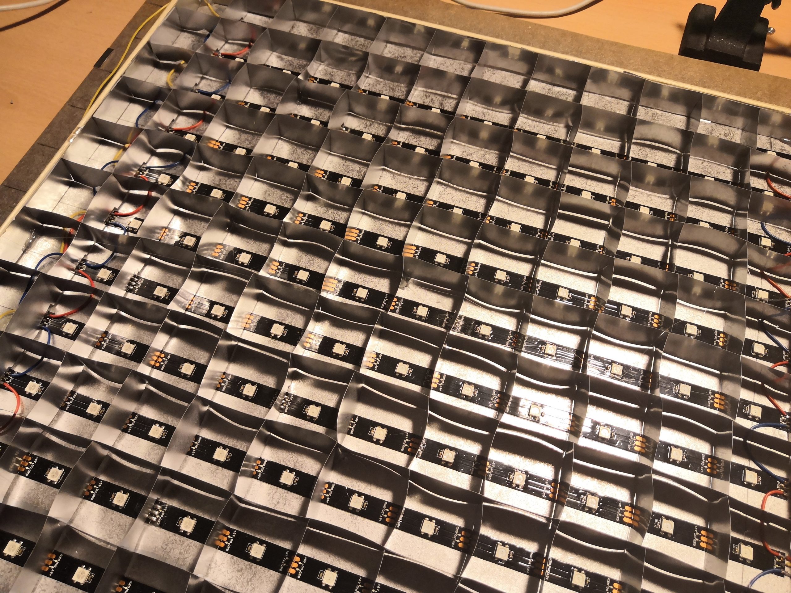
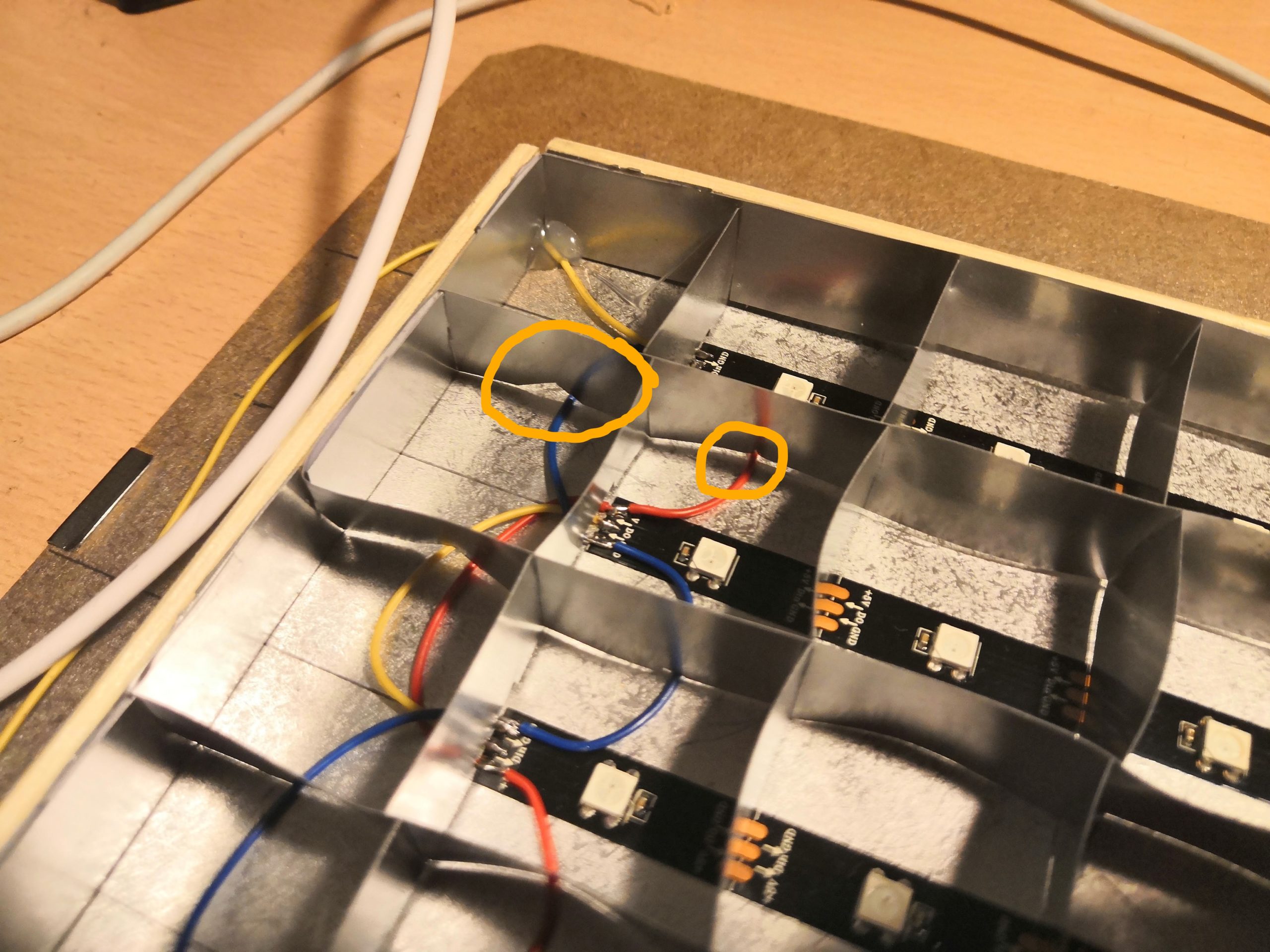
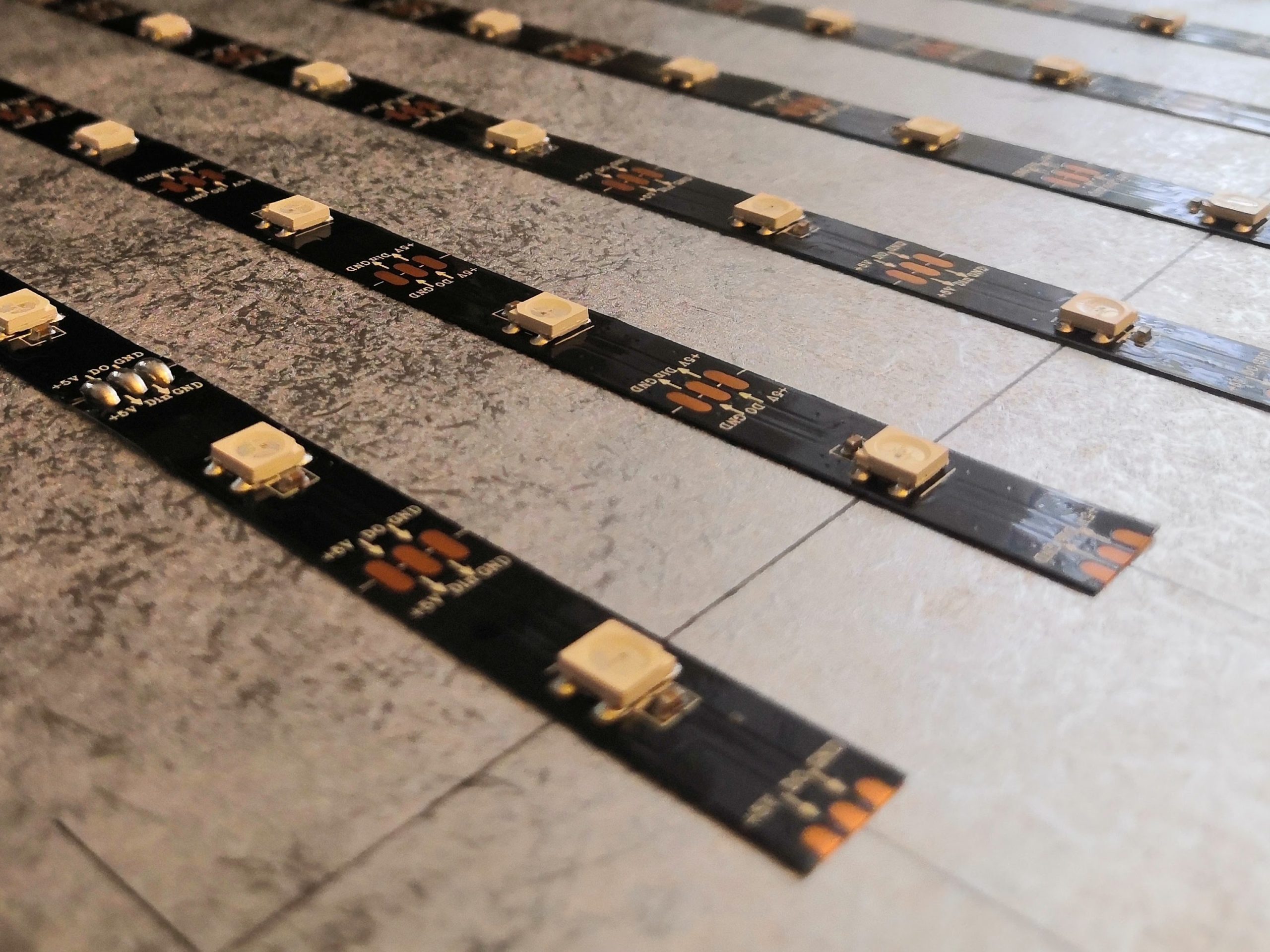
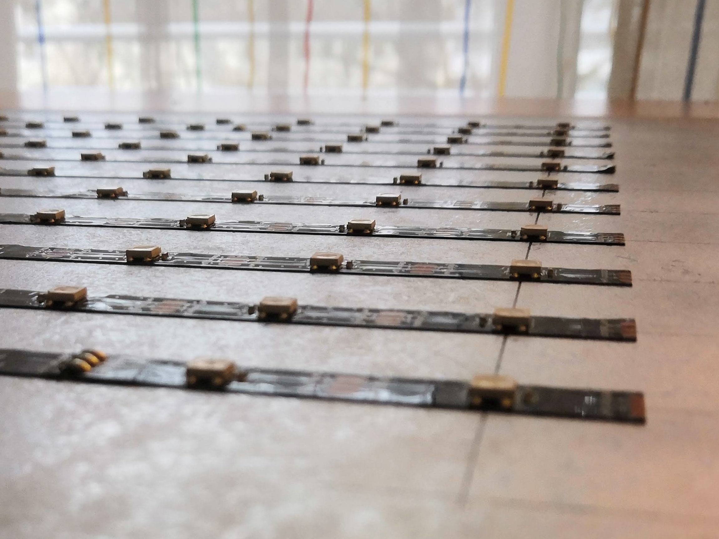
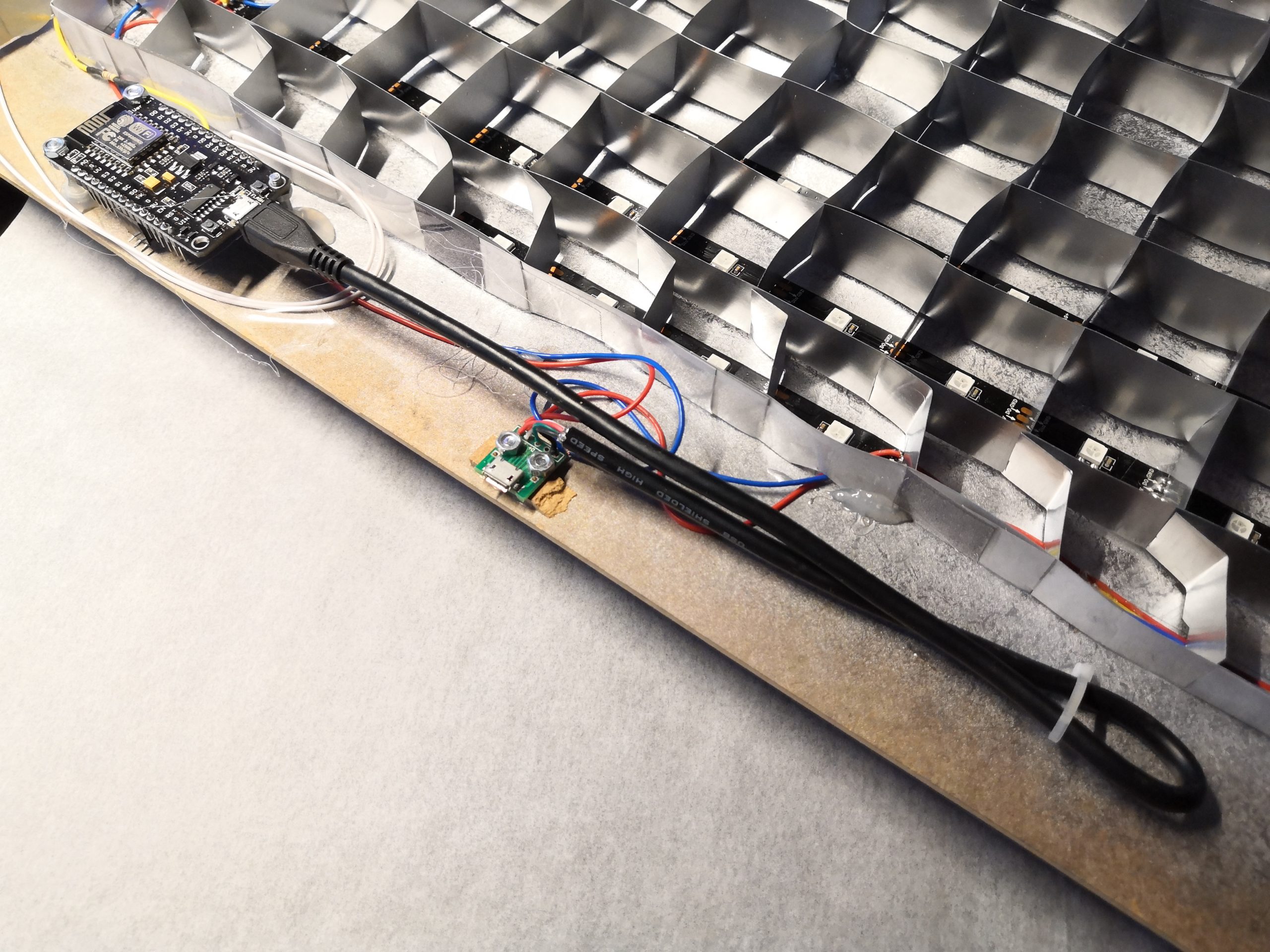
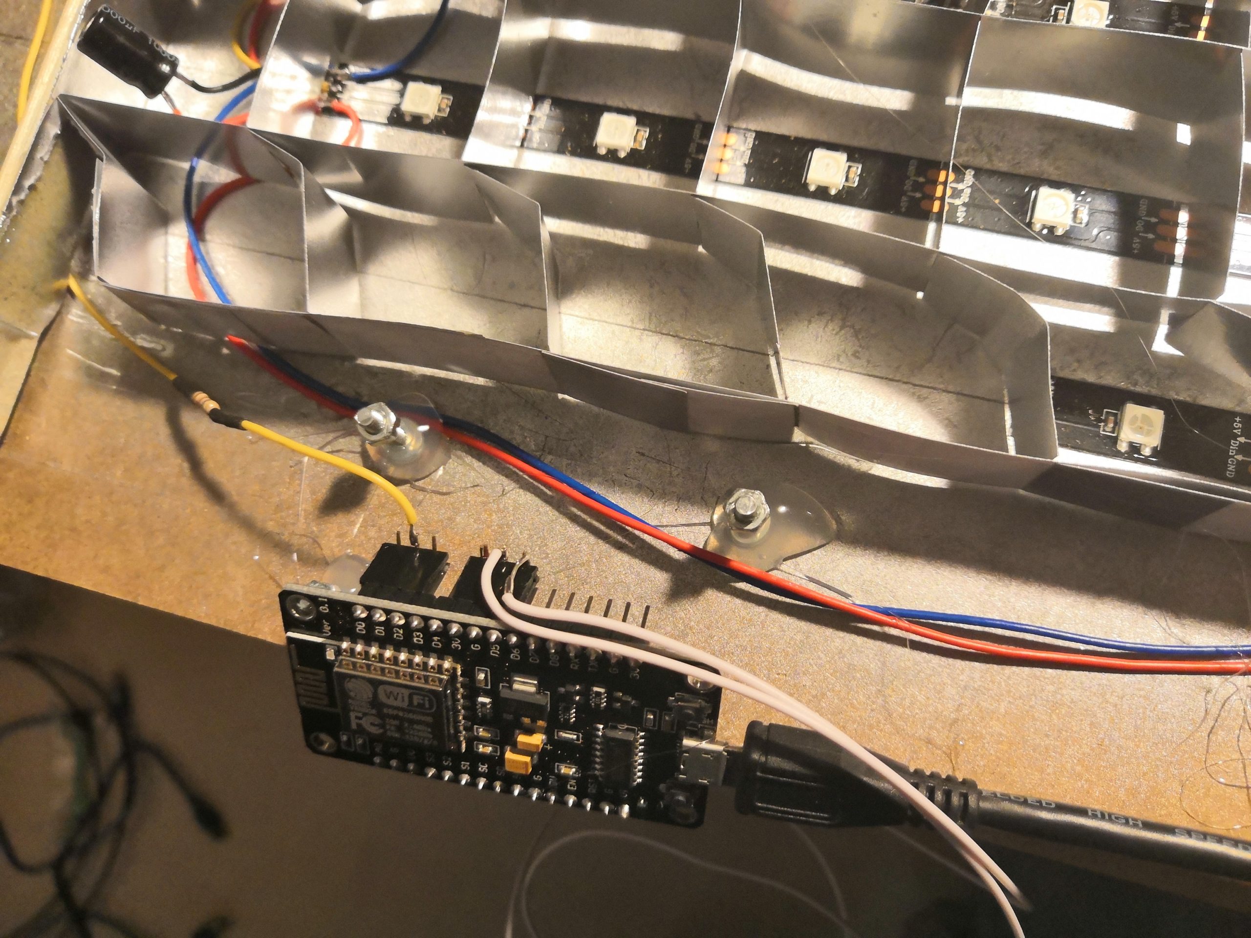
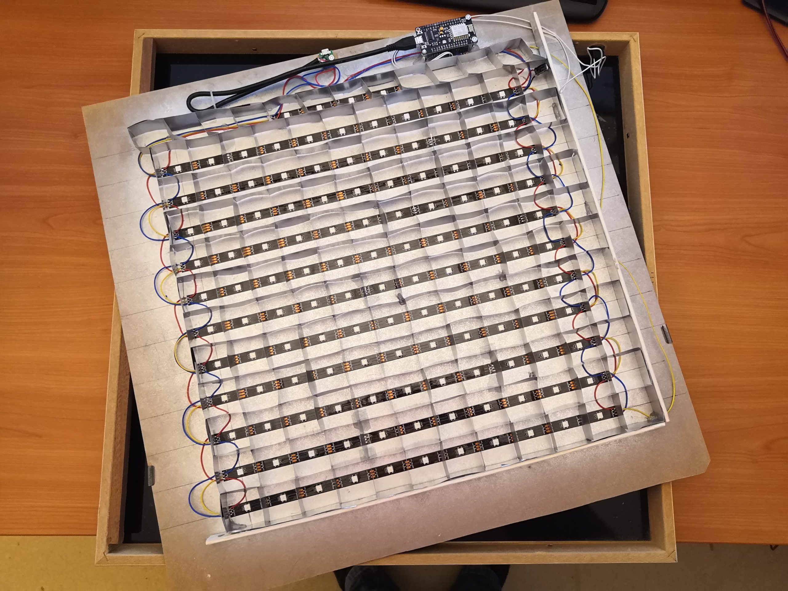
To make the LED matrix, I first divide the long LED strip into 11 strips of 11 LEDs. Then I glued them at a distance of 33mm on the back of the picture frame. I recommend drawing a grid of lines to place the LED strips correctly. As you can see in the pictures below, I spray painted the back with silver/mirror paint to improve the reflections later (You may notice, that in the first version I painted it black to avoid reflection. This time I try it with the mirror color to improve the uniform illumination of the individual letters).
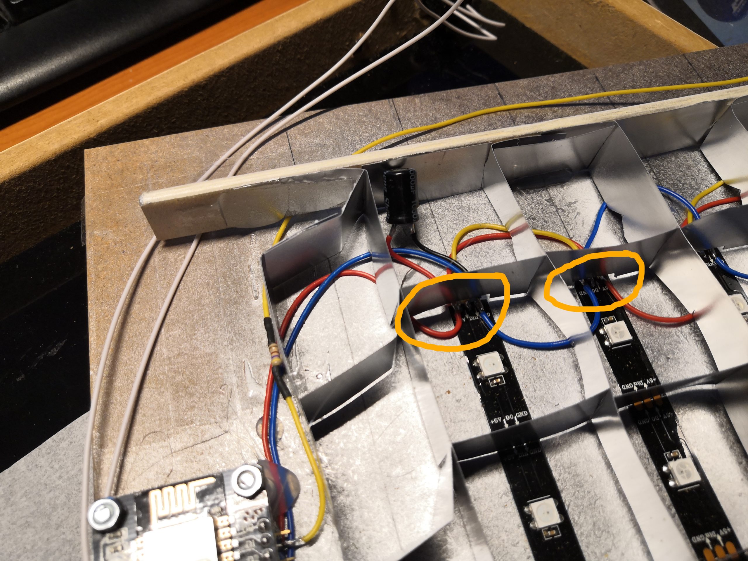
As the twelfth row, I added four additional LEDs, which will later show the minutes on my clock. Very important for the placement is the direction of how the LED strips are arranged. For efficient wiring, a ZIC-ZAC arrangement as shown in the picture is the best.
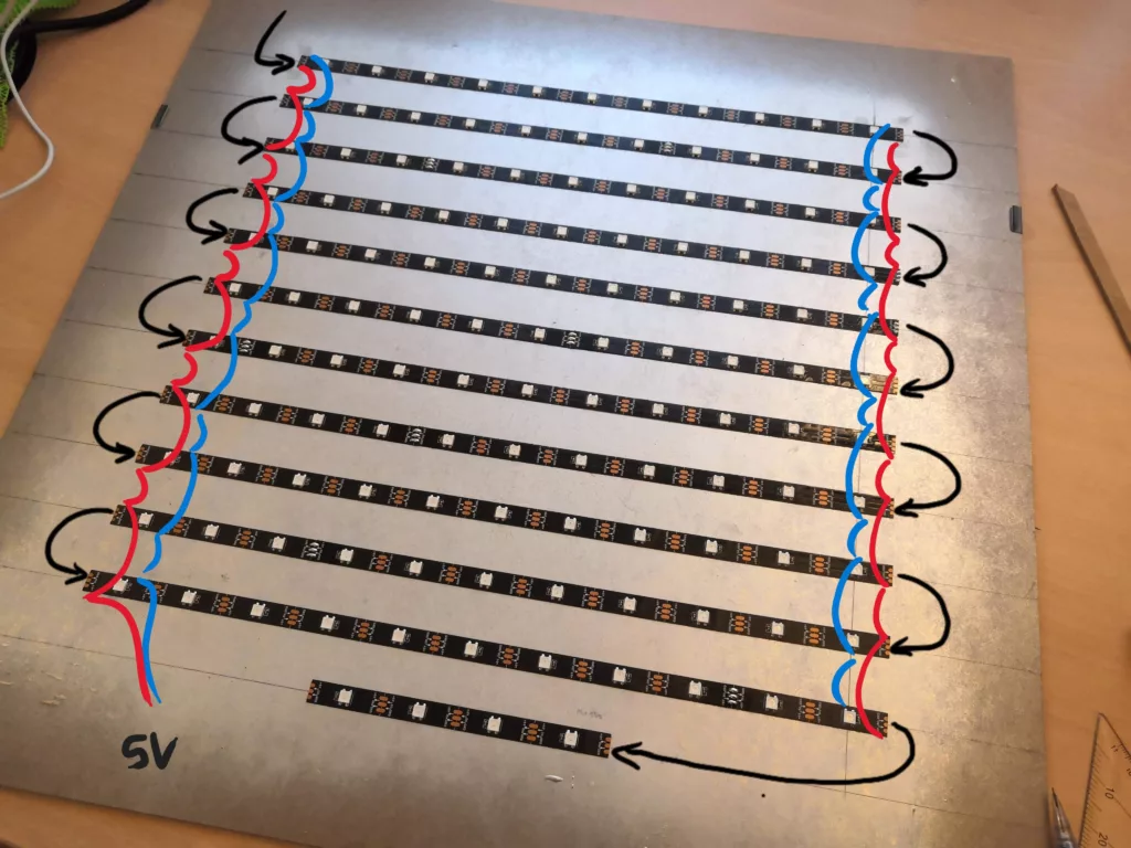
The wiring is not complicated only a bit complex. First I soldered the data line in the ZIC-ZAC pattern so that each DO pin is connected to the next DI pin. Then I soldered all GND and 5V contacts together.
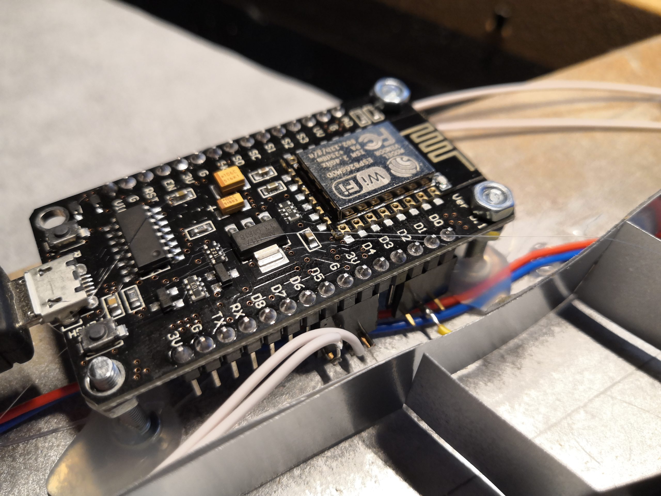
The other electronic components are very manageable. Of course, we need the ESP8266 microcontroller (ESP8266 NodeMCU V3) as the brain of the whole thing, which already has a WLAN interface integrated. Besides that, I only added a 1000 uF capacitor, a 470 Ohm resistor, a push button, and a micro USB connector. The following schematic shows the complete wiring:
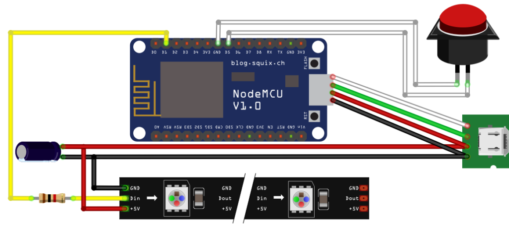


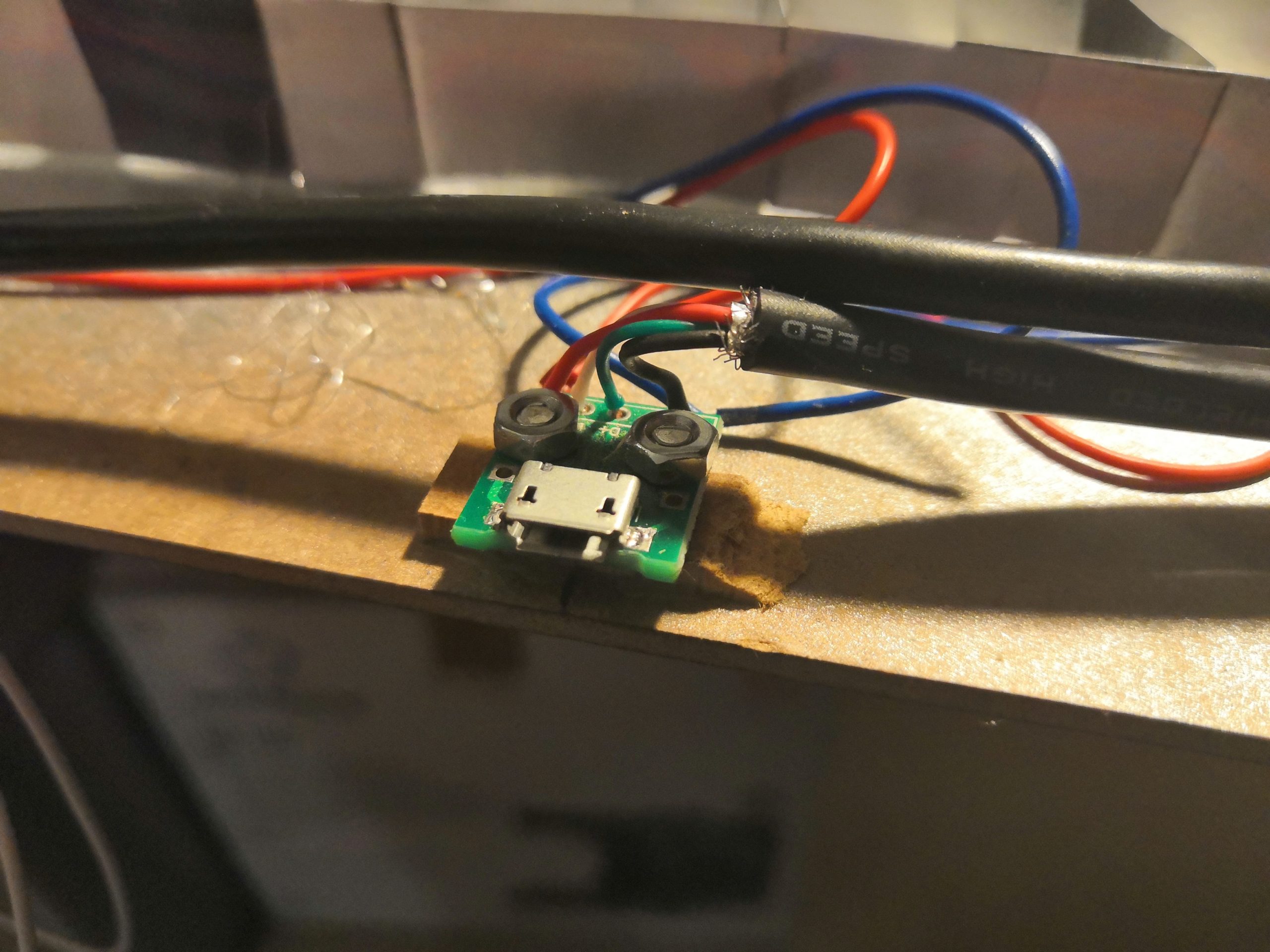
As you can see in the pictures below, I use a micro USB cable to connect the ESP8266 to the micro USB socket. This allows me to program the ESP8266 from outside via the USB socket.
STEP 5: Bring everything together
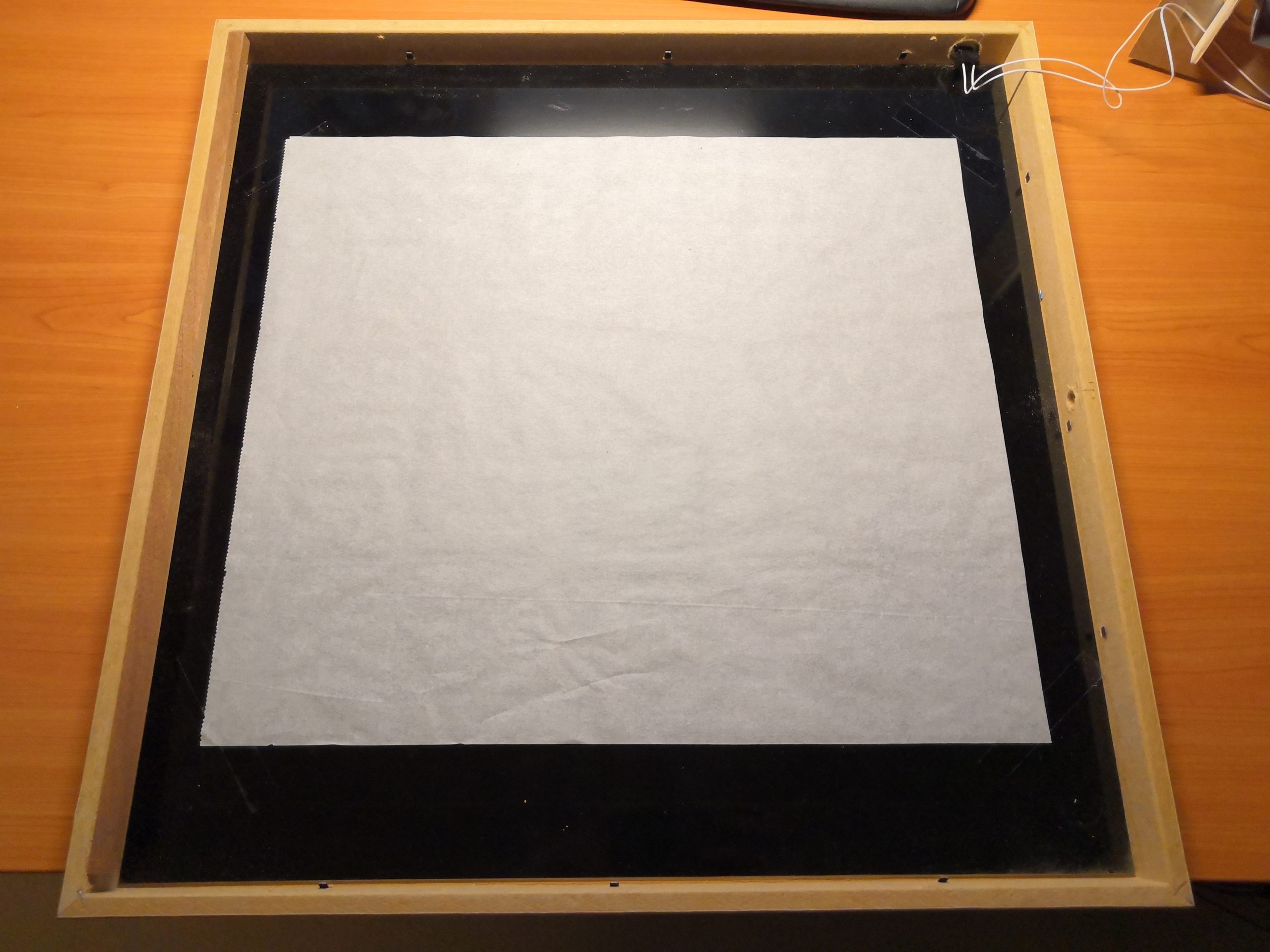
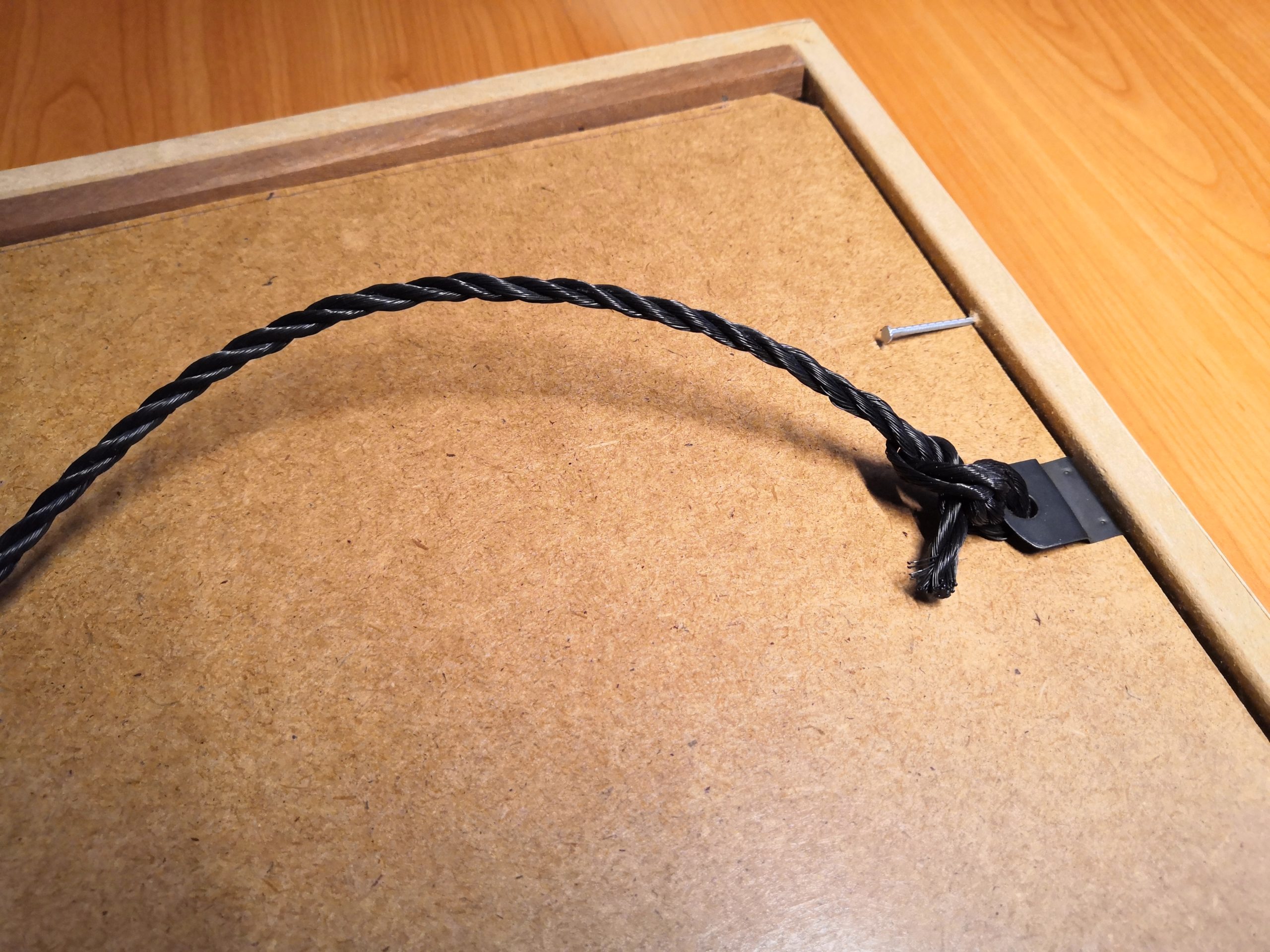
In the final step, I stick a sheet of white backing paper on the back of the glass plate. This results in the wanted diffuse illumination of the individual letters. I glued the light grid with hot glue on the backplate with the LEDs so that everything becomes a solid composition. Now the backplate only needs to be mounted in the picture frame and fastened with four nails.
3. Look at the Heart: The Software
Quickstart
For those who want to get started directly with the code, you can find the complete source code on GitHub:
techniccontroller / wordclock_esp8266
ESP8266 source code for Wordclock 2.0 on GitHub
- Just clone the project into the sketch folder of the Arduino IDE,
- Rename the file example_secrets.h to secrets.h. You don’t need to change anything in the file if you want uses the normal WiFi setup with WiFiManager (see section “Remark about the WiFi setup” in the README.md).
- Install the additional libraries and flash it to the ESP8266 as usual.
- The implemented WiFiManager helps you to set up a WiFi connection with your home WiFi -> on the first startup it will create a WiFi access point named “WordclockAP”. Connect your phone to this access point and follow the steps which will be shown to you.
- After a successful WiFi setup, open the browser and enter the IP address of your ESP8266 to access the interface of the webserver.
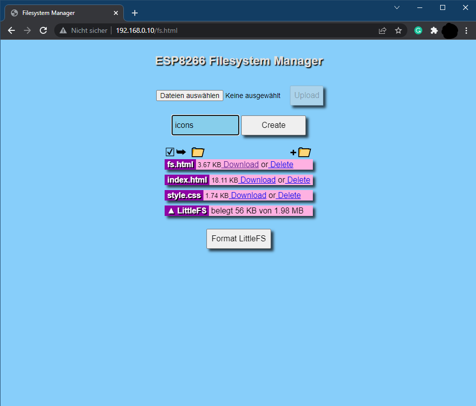
- Here you can then upload all files located in the folder “data”. Please make sure all icons stay in the folder “icons” also on the webserver. The steps for uploading the files should be:
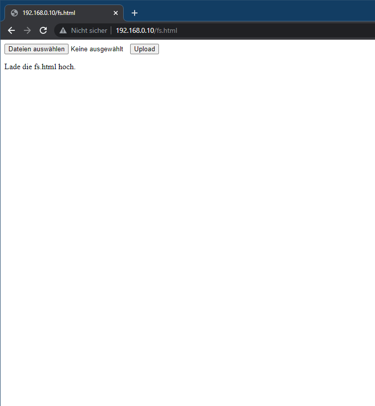
- Open http://<ip-address>/fs.html in a browser
- Upload fs.html
- Upload style.css
- Upload index.html
- Create a new folder icons
- Upload all icons into this new folder icons
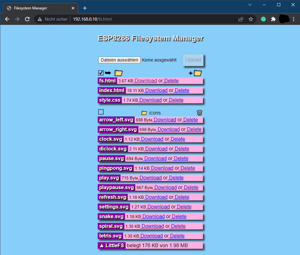
The word clock is now ready. Navigate to http://<ipaddress>/ or http://wordclock.local/ to open the web server interface of the word clock and have fun with it!


Detailed Look
For all others, who want to know more about the software, I would like to explain the different functions in detail. I have rarely developed such a structured Arduino project and it’s worth inspecting the code :). The whole code is well documented.
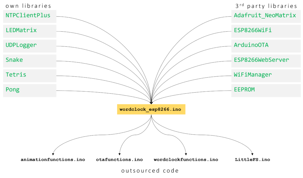
OWN LIBRARIES
NTPClientPlus
Handles all the NTP update stuff, like getting a new time update, converting it to the correct timezone, calculating summer- or wintertime, and splitting the time up in hours, minutes and seconds.
LEDMatrix
Handle all functions related to turning on or off any LED in the Matrix. Provides functions for drawing single pixels, numbers, or characters on the matrix.
It has a low-pass filter function implemented to create smooth transitions between different LED images on the Matrix. The algorithm for that is quite simple. The filtered (to be displayed) color value of a pixel will be calculated like this:
factor = [0...1]
filteredValue_R = currentValue_R + factor * (newValue_R - currentValue_R)
filteredValue_G = currentValue_G + factor * (newValue_G - currentValue_G)
filteredValue_B = currentValue_B + factor * (newValue_B - currentValue_B)
Another neat feature is the LED current limiting and automatic dimming function, which I have implemented in this class. Before writing the color values to the LED strip, the code estimates the total current which is needed to display the given pattern. If the estimated current is above the configurable current limit, it will automatically reduce the overall brightness to meet the total current limit. The code snippet is shown below:
// Calc estimated current (mA) for one pixel with the given color and brightness
uint16_t LEDMatrix::calcEstimatedLEDCurrent(uint32_t color){
  // extract rgb values
  uint8_t red = color >> 16 & 0xff;
  uint8_t green = color >> 8 & 0xff;
  uint8_t blue = color & 0xff;

  // Linear estimation: 20mA for full brightness per LED
  // (calculation avoids float numbers)
  uint32_t estimatedCurrent = (20 * red) + (20 * green) + (20 * blue);
  estimatedCurrent /= 255;
  estimatedCurrent = (estimatedCurrent * brightness)/255;

  return estimatedCurrent;
}

// Draws the targetgrid to the ledmatrix
void LEDMatrix::drawOnMatrix(float factor){
  uint16_t totalCurrent = 0;
  // go over all leds in matrix
  for(int s = 0; s < WIDTH; s++){
    for(int z = 0; z < HEIGHT; z++){
      // inplement momentum as smooth transistion function
      uint32_t filteredColor = interpolateColor24bit(currentgrid[z][s], targetgrid[z][s], factor);
      (*neomatrix).drawPixel(s, z, color24to16bit(filteredColor));
      currentgrid[z][s] = filteredColor;
      totalCurrent += calcEstimatedLEDCurrent(filteredColor);
    }
  }

  // minutes indicator leds
  for(int i = 0; i < 4; i++){
    uint32_t filteredColor = interpolateColor24bit(currentindicators[i], targetindicators[i], factor);
    (*neomatrix).drawPixel(WIDTH - (1+i), HEIGHT, color24to16bit(filteredColor));
    currentindicators[i] = filteredColor;
    totalCurrent += calcEstimatedLEDCurrent(filteredColor);
  }

  // Check if totalCurrent reaches CURRENTLIMIT -> if yes reduce brightness
  if(totalCurrent > currentLimit){
    uint8_t newBrightness = brightness * float(currentLimit)/float(totalCurrent);
    (*neomatrix).setBrightness(newBrightness);
  }
  (*neomatrix).show();
}
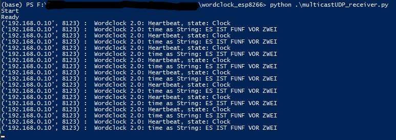
UDPLogger
As the ESP8266 is most of the time not connected to a computer, it would be convenient to still have some information about what the controller is currently doing. I created this library already for previous projects. With this library, you can easily send UDP multicast messages into the network and everyone in the network can receive these messages. I wrote a small python script (multicastUDP_receiver.py) that can receive and display the messages.
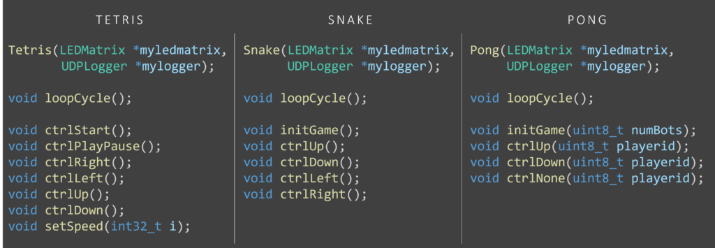
Snake, Tetris, Pong
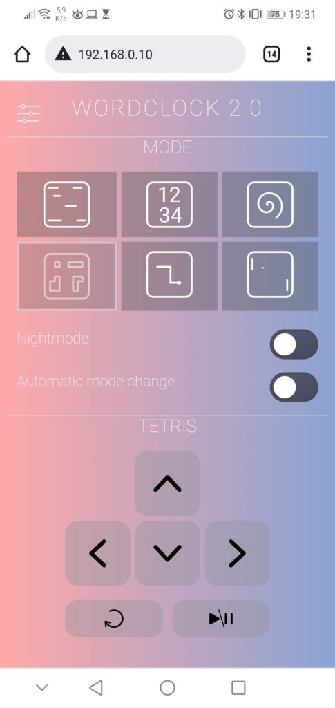
All these classes are structured similarly. They contain the algorithm for the games which can be played via controls from the webserver. So each class has some update function, which is called in every cycle to draw potentially new pixels on the matrix. Also, each class has one or more control functions which can be called when the user triggers some action from the web server interface (e. g. turn left, turn up, rotate,…).
OUTSOURCED CODE
animationfunctions.ino
In this file, I moved all functions, which are needed for the animation. So for example the SPIRAL animation and the animations for the random SNAKE or TETRIS game (if the clock is set to automatic state-changing mode, the different game states will show a random animation of their game). In the outsourced functions, I used as few as possible global variables, so if a variable needs to be available for the next execution of the function, I used static variables.
otafunctions.ino
Contains all the functions needed to set up ArduinoOTA updates. Is just the setupOTA() and handleOTA() function. Nothing fancy, just to get this standard code out of the main file.
wordclockfunctions.ino
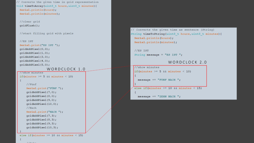
This file contains some interesting functions. Most of the word clocks out there uses some kind of direct mapping from time values (hour and minute) to LED coordinates on the word clock. One disadvantage is that when you change the layout of the word clock (e. g. more rows, more columns, another language, …) you need to do the whole mapping again. I did this in my first version as well and had to deal with a lot of x and y coordinates.
This time I use a different approach, instead of doing a mapping from time to coordinates, I split this task up into two parts. Firstly, a mapping from time value to words (or sentence) and secondly a mapping from words (or sentence) to coordinates. The first mapping is still a little bit of work, but instead of dealing with coordinates, you can easily write down the strings that correspond to the specific time value. In the following picture, you can see a short comparison of the code amount of both approaches.
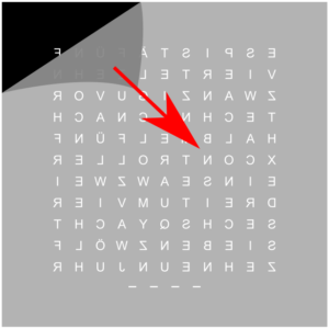
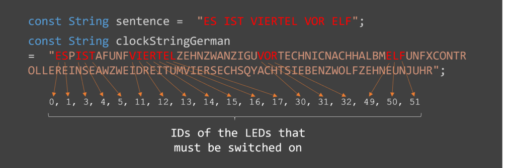
What about the second mapping? The great thing about the seconds mapping is that we can implement it completely generic. This means if we have a string representation of the whole word clock, we can easily fit a given sentence in it and so automatically identify which LEDs need to be switched on. An example is shown in the figure below.
LittleFS.ino
This file is an unchanged takeover from https://fipsok.de/Esp8266-Webserver/esp8266. It provides a very nice file manager for the easier upload of files to ESP8266.
FAQ – Customization
What do I have to change if I use a different layout or a different language?
The Wordclock is available in German, English, and Italian language. By default the language is German. To use the English or Italian language please replace the file wordclockfunctions.ino with wordclockfunctions.ino_english or wordclockfunctions.ino_italian. The code compiles only with one file named wordclockfunctions.ino. So please rename the file you want to use to wordclockfunctions.ino and replace the existing file.
To use a custom layout, you have to do the following:
• in the wordclockfunctions.ino change the variable clockStringGerman according to your layout.
• in the wordclockfunctions.ino change the function timeToString() so that your wished sentence (e. g. “IT IS ONE OCLOCK”) is created based on the given hours and minutes value.
What do I have to change if I use only 10 rows instead of 11?
You have to do the following (But keep in mind that due to the letter size, the digital clock mode does not look good with only 10 rows):
• in ledmatix.h, tetris.h and wordclock_esp8266.ino change the line
#define HEIGHT 11to
#define HEIGHT 10• in pong.h and snake.h change the line
#define Y_MAX 11to
#define Y_MAX 10• in the wordclockfunctions.ino change the variable clockStringGerman according to your layout.
• in ledmatrix.cpp change the line
(*neomatrix).drawPixel(WIDTH - (1+i), HEIGHT, color24to16bit(filteredColor));to
(*neomatrix).drawPixel(i, HEIGHT, color24to16bit(filteredColor)); (this needs to be changed, as the minute indication LEDs are now at the beginning of the last row instead of the end).
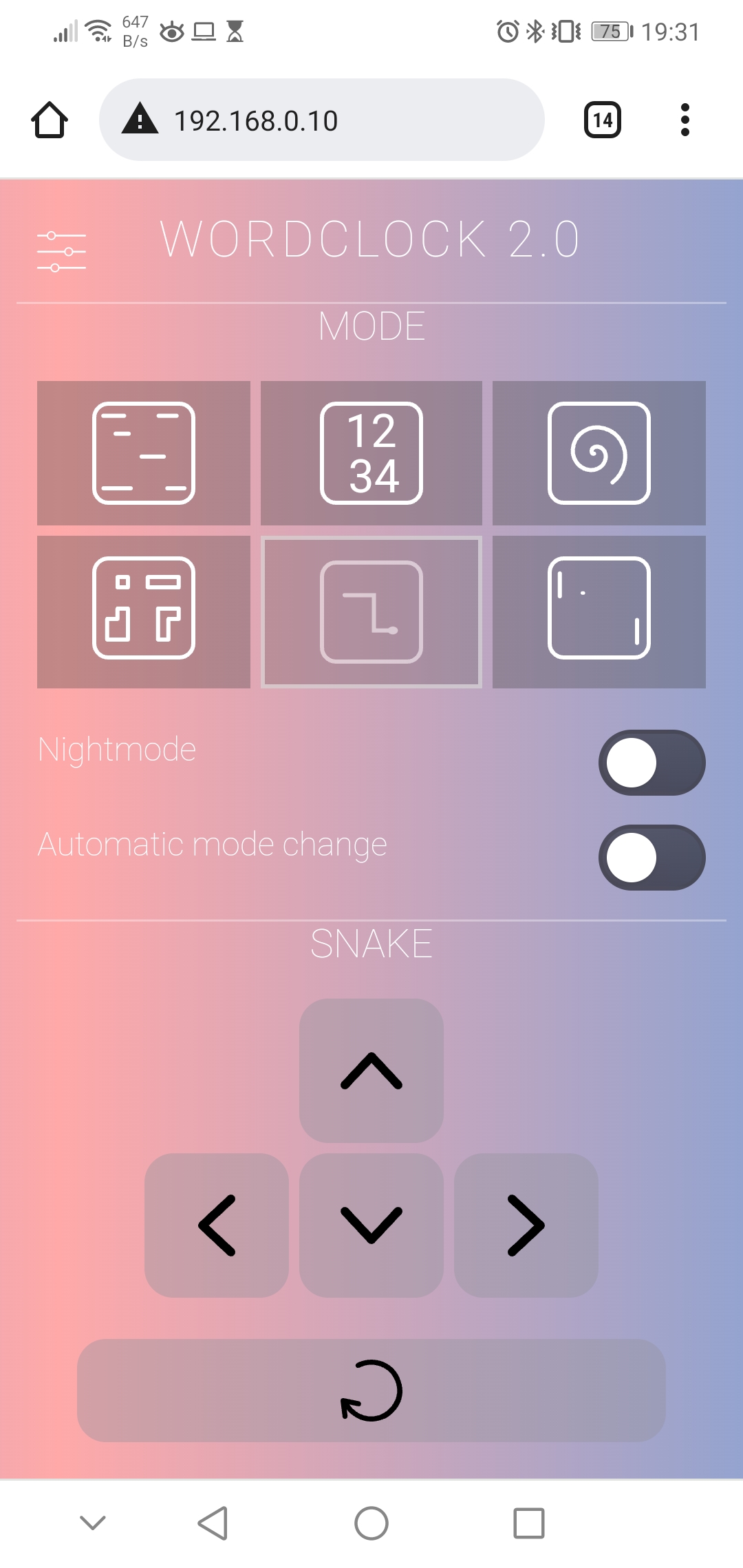
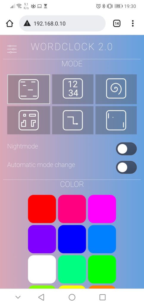
Modes of the word clock
One can change the different modes by a short press on the physical push button in the picture frame or by selecting it in the web interface. In the web interface, there is also the option to enable an automatic mode change every 10 seconds. If this function is active the game modes TETRIS, SNAKE and PONG will just play an animation without user interaction.
I additionally implemented a night mode that turns off all LEDs. The clock enters night mode at a specific time, which can be configured in the settings menu of the web interface. The night mode can also be activated at any time directly via the web interface or a long press on the physical push button.
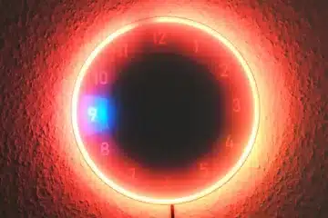
Word clock
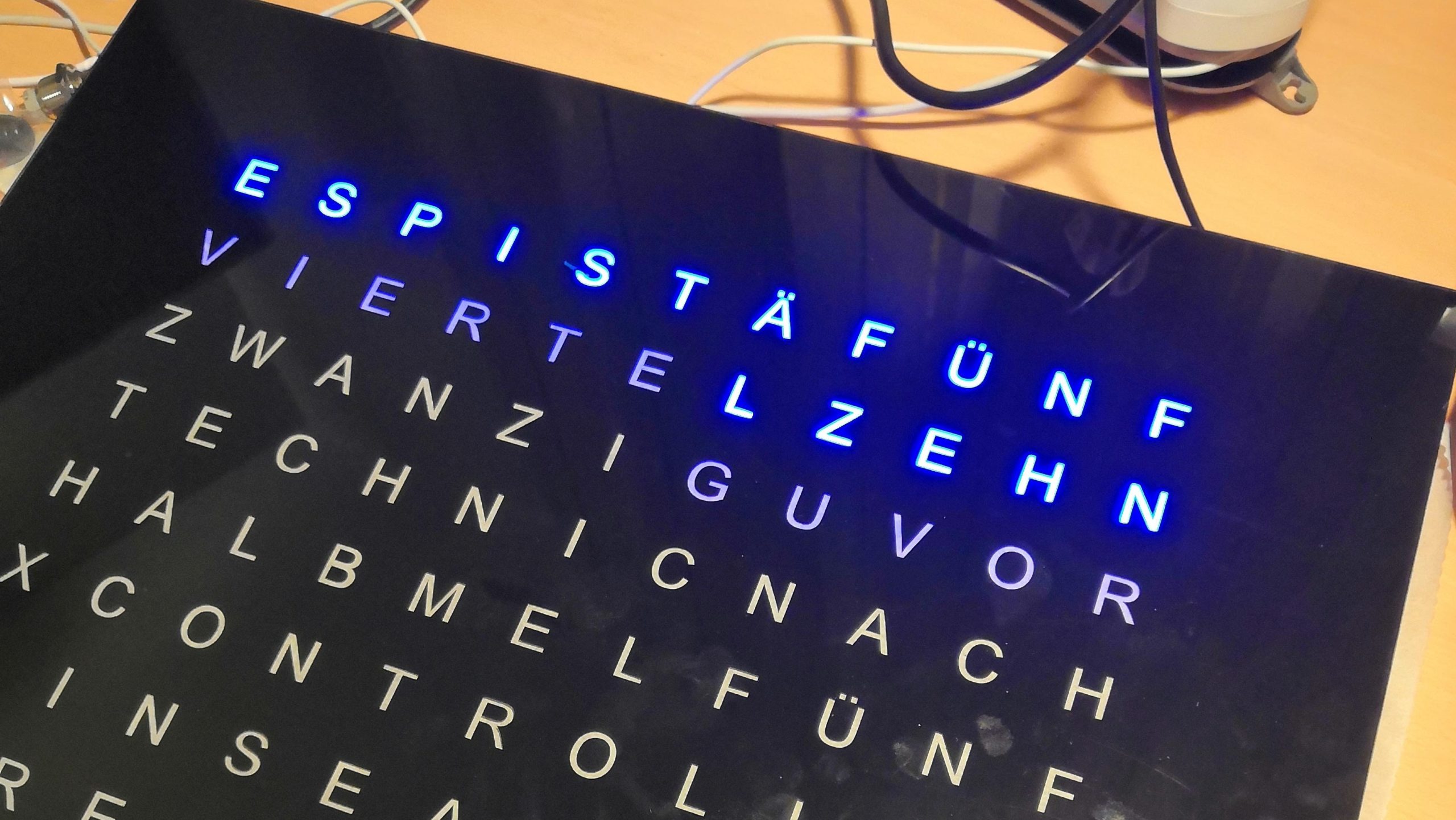
Standard mode which is active after startup is of course the normal word clock mode, where the clock displays the time as text.
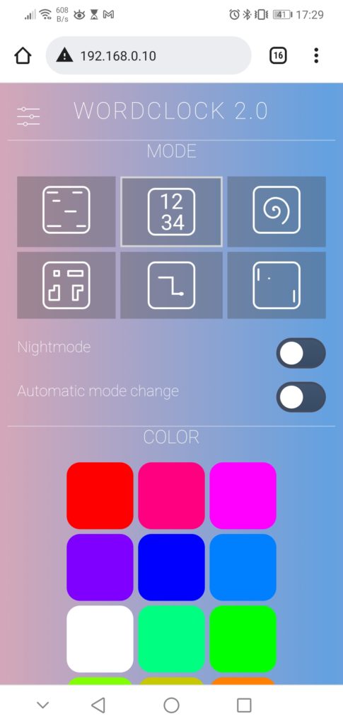
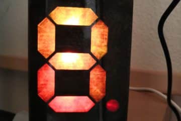
Digital clock
The second mode also displays the time, but as digits drawn on the LED matrix. This is only possible because of the 11th row so that I can construct two lines of 5 row high digits with one empty line in between.
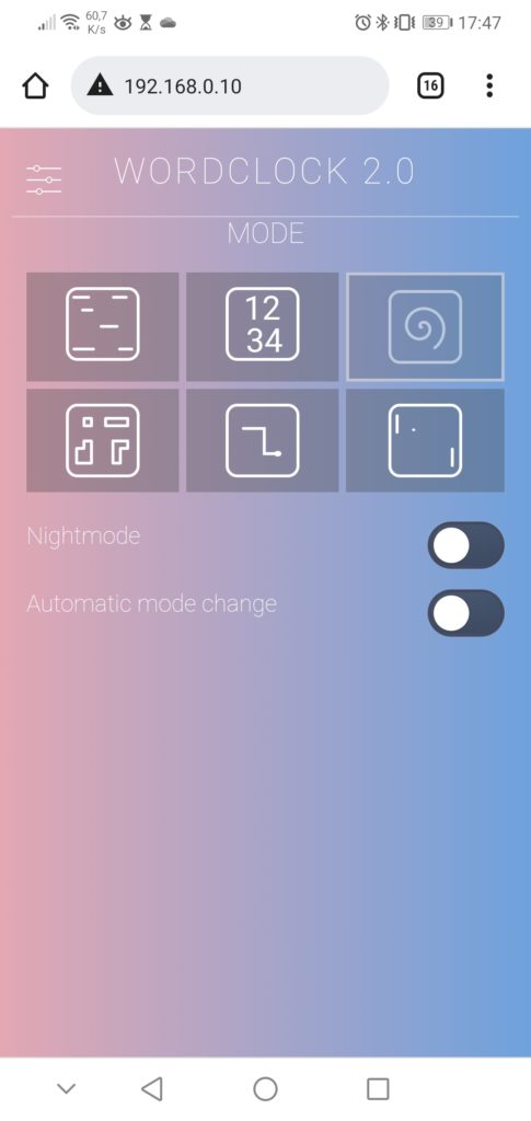
SPIRAL animation
In this mode, the clock displays a spiral animation with changing colors.
TETRIS game
Tetris is one of three game modes, which can be controlled via the web interface. I have not written the core game code of those three games completely myself. Instead, I used some code parts from here as a basis and integrated them into my object-oriented software. The code for the random animation of Tetris and Snake is a takeover from my previous LED-Matrix project.
SNAKE game
Here you can control a snake to catch the randomly placed apple. Well, just the traditional Snake game, I don’t think I need to explain much more.

PONG game
For Pong, you need usually two players. But, I extended the code by a bot that can control just one or both paddles. So the user can control the right paddle via the web interface or let the bot take over the paddle movement in case of the animation mode.
Have fun rebuilding it! If you have any questions, please feel free to write a comment.
161 Comments
Clyde · 05/01/2024 at 13:31
Hi Edgar,
super Projekt, feiere ich sehr hart!
Alles bestens, aber ich würde gern was fragen was ich nicht kapiere. Die Zeit konvertierung auf “time to string” scheint im Englischen irgendwann auseinander zu laufen (+1h).
Wordclock 2.0: NTP running
Wordclock 2.0: Time: 13:23:50
Wordclock 2.0: TimeOffset (seconds): 3600
13
23
IT IS TWENTY MINUTES PAST TWO
Das passiert nach einer gewissen Zeit, nach dem flashen (so scheint es mir) funktioniert es eine Zeit lang. Danach wird bei der Stunde eine zu viel dargestellt? Ich hab schon einiges probiert, aber nichts hat wirklich funktioniert. Hast du ggf. eine Idee warum das passiert?
Ich habe den content von wordclockfunctions.ino mit der englischen version überschrieben.
Danke – ich such selber weiter – aber sachdienliche Hinweise, wären fantastisch 🙂
Danke cheers clyde
clyde · 05/01/2024 at 13:39
Schaut aus als würde der Fehler in irgendwo mit dem “past” zusammenhängen.
Hier mal das Log mit dem Sprung von falsch zu richtig.
13
34
IT IS HALF PAST TWO
Wordclock 2.0: time as String: IT IS HALF PAST TWO
Wordclock 2.0: Heartbeat, state: Clock, FreeHeap: 36192, HeapFrag: 2, MaxFreeBlock: 35552
13
35
IT IS TWENTY FIVE MINUTES TO TWO
Wordclock 2.0: time as String: IT IS TWENTY FIVE MINUTES TO TWO
Wordclock 2.0: Heartbeat, state: Clock, FreeHeap: 36192, HeapFrag: 2, MaxFreeBlock: 35552
clyde · 05/01/2024 at 14:44
It seems like this.
14
20
IT IS TWENTY MINUTES PAST THREE
Same issue. Also in der wordclockfunctions.ino_english schaut es nach dem Prob aus. Hoffe das hilft zum troubleshooten.
Techniccontroller · 05/01/2024 at 15:16
Hallo Clyde,
danke für deinen Kommentar. Der Fehler liegt in in Zeile 158 der Datei wordclockfunctions.ino_english. Statt
if(minutes >= 20)
  {
      hours++;
  }
muss es so aussehen:
if(minutes >= 30)
  {
      hours++;
  }
Der Fehler hat sich aus dem Deutschen eingeschlichen, wo ich statt “zwanzig nach 2”, “zehn vor halb 3” anzeige.
Ich habe den Fehler auf GitHub korrigiert.
Vielen Grüße
Edgar
clyde · 05/01/2024 at 15:38
Unglaublich schnelle Antwort.
Ich hatte diese Zeilen in Vermutung 🙂 aber 2 Gehirnzellen haben nicht ausgereicht um auf die richtige Idee zu kommen. Wird gleich geändert und ausprobiert.
Consider it DONE 🙂 falls melde ich mich.
Merci für den schnellen fix
Maximilian Bauer · 31/12/2023 at 21:05
Hallo Edgar,
Ein echt tolles Programm was du hier geschrieben hast. Ich habe die Uhr nun an den tollen IKEA Rahmen angepasst und sie läuft tadellos.
Das einzige Problem was derzeit vorliegt, ist, dass die Uhr sich nach einer gewissen Zeit einfach abschaltet. Ist irgendwo ein Timmer für den Standby Modus hinterlegt?
Ich dank dir schon mal herzlich für deine Antwort und wünsche einen guten Rutsch ins neue Jahr 🙂
Techniccontroller · 01/01/2024 at 14:37
Hallo Maximilian,
danke für deinen Kommentar. Ich habe keinen Standby-Timer implementiert. Aktuell kann ich mir nur zwei Gründe für dein beschriebenes Verhalten vorstellen.
1. Es könnte sein, dass die Uhr in den NightMode wechselt (alle LEDs sind aus). Die Einschaltzeit des Nightmodes kann über das Webinterface der Uhr eingestellt werden. Prüfe mal ob da sinnvolle Uhrzeiten drin stehen. Wenn du keinen Nightmode verwenden möchtest, müsstest du eben eine sehr kurze Zeitspanne (z. B. eine Minute um 3 Uhr Nachts) einstellen.
2. Die zweite Möglichkeit wäre, dass die Uhr aufgrund einer fehlerhaften Internetverbindung nach einer gewissen Zeit neu startet. Davon sollten die LEDs aber nicht dauerhaft ausgehen. Im Idealfall bekommst du davon vermutlich nichts mit, daher würde ich das erstmal als Fehlergrund ausschließen. Wenn du genauer analysieren möchtest, müsstest du die Logging Nachrichten der Uhr aufzeichnen, wie ich es in der README auf GitHub beschrieben habe.
Ich hoffe ich konnte dir damit helfen und wünsche dir noch viel Spaß mit der Wortuhr.
Viele Grüße
Edgar
Maximilian Bauer · 01/01/2024 at 14:46
Hallo Edgar,
ein frohes neues Jahr wünsche ich dir 🙂
Also ich habe nun das mit dem NightMode getestet und festgestellt, dass es damit zusammenhing. Verblüffend war nur, dass ich den NightMode ausgeschaltet hatte. Nun habe ich auf Nachts 3 Uhr für zwei Minuten den NightMode aus und alles funktioniert. Die Uhr ist so toll und ein echter Hingucker. Vor allem, dass sie nun so perfekt in den IKEA Rahmen passt. Wenn du die Pläne mit in deine Unterlagen aufnehmen möchtest, gib mir gerne Bescheid. Ich habe die in Autocad als DXF konstruiert und auch für die Drahtbrücken gleich Löcher vorgesehen. Sollte also Interesse bestehen, so schreibe mich einfach an 🙂
Ich wünsche noch einen schönen Tag.
Andreas · 07/12/2023 at 22:22
Hallo Edgar,
vielen Dank für das Wahnsinns-Projekt!!
Eine Kleinigkeit würde ich gerne noch hinzufügen und zwar einzelne Buchstaben anzeigen lassen, indem ich die LEDs als Pixel benutze (so wie du es beim Anzeigen von “IP” der IP-Adresse machst.)
Wo muss ich die Info, welche LED-Positionen für verschiedene Buchstaben leuchten müssen, denn hinterlegen? In “own_font.h” ?
Danke schon mal!
Techniccontroller · 08/12/2023 at 8:21
Hallo Andreas,
danke für dein Kommentar.
Ja genau die LED-Positionen, welche leuchten sollen, sind in der Datei ‘own_font.h’ definiert. Dort habe ich eine Array für Zahlen und eins für Buchstaben. Für Zahlen hab ich es vollständig (0-9), für die Buchstaben nur ‘I’ und ‘P’ definiert. Wenn du weitere Buchstaben anzeigen willst, müsstest du sie hier definieren.
Zudem musst du dann noch das Mapping zwischen Buchstabe und Index im Array anpassen, damit das Programm weiß an welcher Stelle im Array welcher Buchstabe definiert ist. Das passiert in der Funktion ‘printChar()’ in der Datei ‘ledmatrix.cpp’. Hier müsstest du, nach Vorbild der bereits definierten Mappings für ‘I’ und ‘P’, deine Mappings ergänzen.
Sobald du deine Buchstaben definiert hast, kannst du sie mittels eines Aufrufs der Funktion ‘ledmatrix.printChar(…)’ auf der LEDMatrix anzeigen. Bitte nicht vergessen danach auch ‘ledmatrix.drawOnMatrixInstant()’ auszuführen um die Buchstaben tätsächlich auf der Uhr leuchten zu lassen. Du kannst dich ja an das Beispiel in den Zeilen 360-366 in ‘wordlock_esp8266.ino’ halten, wo ich die IP-Adresse anzeige.
Viele Grüße
Edgar
Andreas · 08/12/2023 at 21:57
Hallo Edgar, vielen dank für die schnelle Rückmeldung. Hast du zufällig vielleicht eine Idee was der beste Ansatz wäre, um die Buchstaben im “Scrolling”-Modus anzeigen zu lassen?
Falls du da ein paar Schlagwörter oder ein online verfügbare Funktion parat hast.
Falls nicht, auch kein Problem 🙂
Danke!
Techniccontroller · 09/12/2023 at 9:54
Hallo Andreas,
scrollen hab ich selbst noch nicht implementiert und ist tatsächlich auf diesen kleinen Microcontrollern etwas komplexer.
Die einfachste Methode ist es ein 2D-Array mit der kompletten Anzeige (11x??) zu erstellen und dann in einem festen Zeitintervall immer ein Fenster mit 11 Zeilen/Spalten über das Array zu schieben und auf die LED-Matrix zu übertragen.
Je nachdem wie lang der Text ist, denn zu anzeigen möchtest könntest du in ein Arbeitspeicherproblem laufen (passiert recht schnell, ich denke mehr als dreimal so groß wie die Matrix kannst du das Array nicht machen).
Das heißt dann musst du kreativ werden.
Entweder das Array nur binär ohne Farbwerte speichern und erst beim Übertragen Farbe hinzufügen (ähnlich wie ich es beim speichern der Font gemacht habe).
Oder alternativ den Text nur als String speichern und on-the-fly beim scrollen, jeweils die font neu auslesen und auf die Matrix übertragen.
Zweiteres ist sehr aufwendig und komplex, aber natürlich die elegante und am besten skalierende Lösung. Ersteres bekommt mal schneller implementiert.
Ich selbst habe wie gesagt beides noch nicht implementiert. Ich hoffe ich konnte trotzdem helfen.
EDIT: Ich hab gerade nochmal nachgesehen, der ESP8266 hat deutlich mehr RAM als ich erwartet hatte (160kB), es kann daher sein, dass die Speicheroptimierung die ich oben beschrieben habe gar nicht nötig ist.
Viele Grüße
Edgar
André · 21/11/2023 at 21:32
Lieber Edgar
ganz herzliche Gratulation zu deinem einzigartigen und tollen Projekt und dafür, dass du es teilst. Ich bin intensiv mit dem Nachbau beschäftigt und bald sollte ich auch alle benötigten Komponenten beisammen haben.
Beim überprüfen des Codes erscheint mir allerdings bei Zeile 695 diese Fehlermeldung:
‘Base64’ was not declared in this scope; did you mean ‘base64’?
Im Voraus besten Dank für deinen Ratschlag und schöne Grüsse.
André
Techniccontroller · 22/11/2023 at 9:55
Hallo André,
es freut mich, dass dir mein Projekt gefällt.
Aus der Ferne kann ich zu deinem Problem nur allgemeine Tipps geben:
1. Du hast die aktuelle Version der Arduino IDE (1.8.19 oder 2.2.1) installiert?
2. Du hast das komplette Arduino Projekt von GitHub heruntergeladen?
3. Du hast die benötigten Bibliotheken installiert wie in der README auf GitHub beschrieben? (Base64 ist keine Bibliothek, die du installieren musst, sie ist bereits in meinen Arduino Projekt enthalten. Die Variable Base64 ist in Base64.cpp definiert. Du kannst prüfen ob diese Datei im Projekt vorhandenen ist.)
4. Du hast den ESP8266 Arduino Core mit den Board Informationen installiert, wie in README beschrieben?
Wenn du all diese Punkte nochmal gecheckt hast, und am Code sonst nichts geändert hast und das Problem immer noch auftritt müsstest du mir mehr Informationen zur Verfügung stellen. Zum Beispiel die komplette Ausgabe des Compilers. Das dann gerne auch per Mail (Impressum).
Viele Grüße
Edgar
Lars L · 16/11/2023 at 17:55
Hallo,
erstmal ein Riesen Kompliment für die tolle Arbeit! Ein wundervolles Projekt! Ich hätte zwei Fragen. Was muss ich am Code anpassen für mein Layout?
Mein Anschluss der Strips liegt unten links also LED Nummer 0 ganz oben in der Mitte sind die Minutenpunkte angeordnet also am Ende.
Über eine Antwort würde ich mich sehr freuen! Wie kann ich dir etwas in die Kaffeekasse füllen?
VG
Lars
Techniccontroller · 17/11/2023 at 11:40
Hallo Lars,
vielen Dank für dein Interesse an meiner Wordclock.
Deine Anpassung ist sehr einfach zu implementieren. Ich habe kurz einen neuen Branch auf GitHub mit deinen Änderungen gemacht. Die kannst du direkt in deinen Code übernehmen:
https://github.com/techniccontroller/wordclock_esp8266/commit/68b37d2cd82d4ee63fac9e7e055e3cda3969921d
Ich kann diese Änderungen leider nicht testen, sag deshalb bescheid, falls es nicht wie erwartet funktioniert.
Viele Grüße
Edgar
PS: Hier ganz unten auf Seite hab ich einen Link zu PayPal 🙂 Vielen Dank.