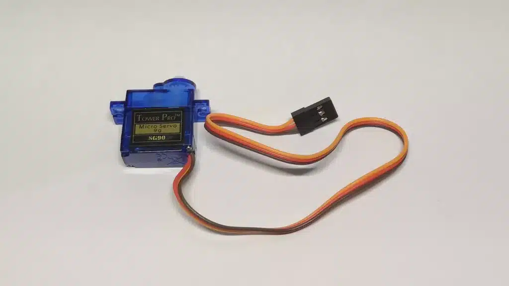
I am currently in the process of designing and building a five-axis robot from scratch. I, therefore, also need a gripper to be able to manipulate objects. The drive for the gripper should be a commercially available micro servo, as shown in the following picture. In addition, the gripper should have parallel closing fingers to be able to grip objects securely. While searching for existing 3D models for grippers on well-known websites such as GrabCAD and Thingiverse, I unfortunately did not find any suitable ones. Therefore, in this post, I would like to present my own design of a 3D printed parallel gripper for a micro servo. There will be a separate post about the whole robot soon.
Design
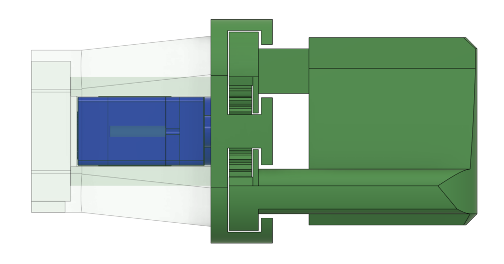
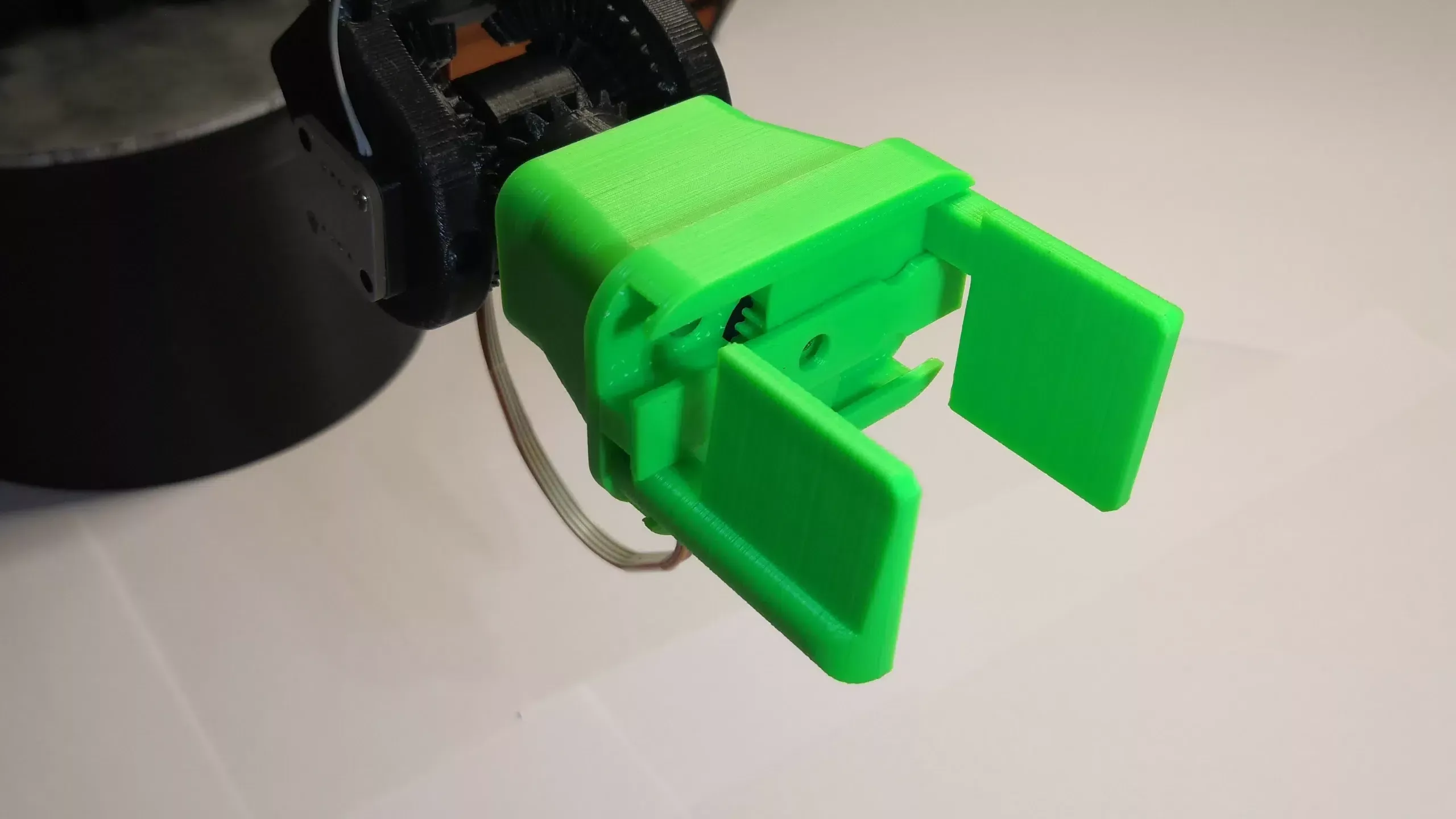
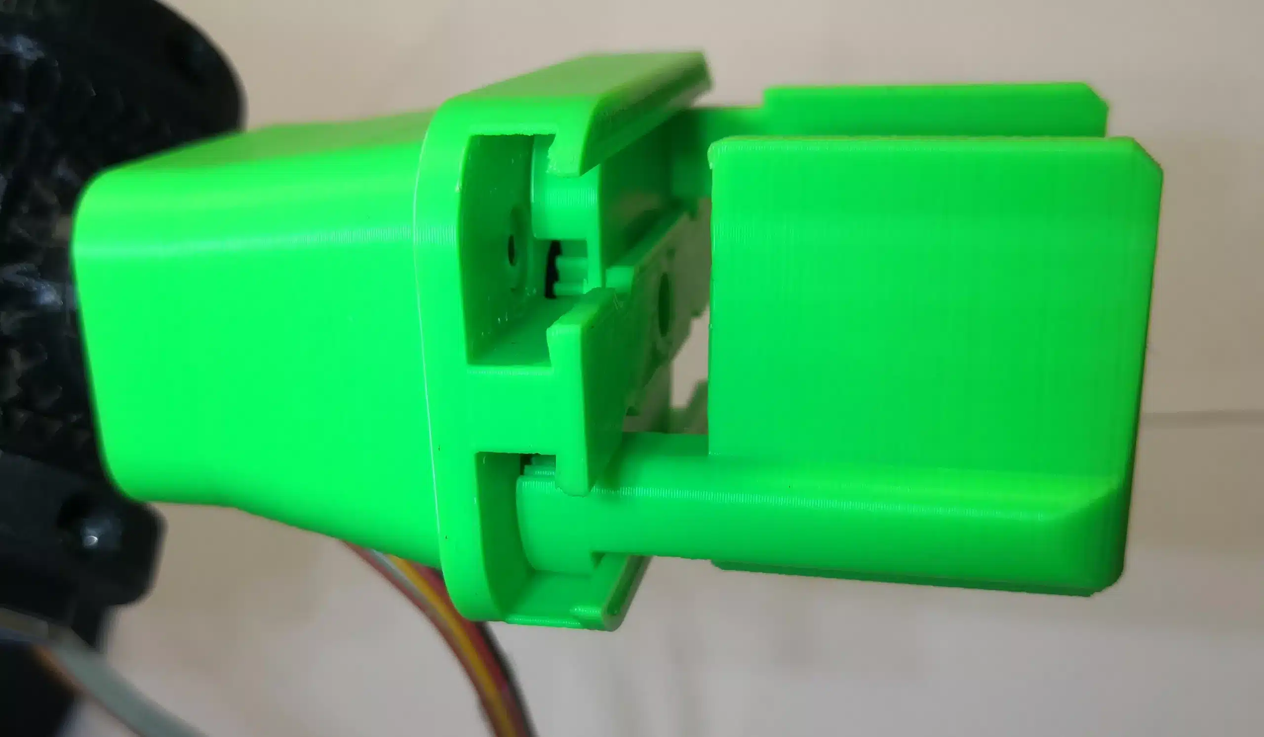
The servo can perform a rotation of about 180°. This rotational movement must, therefore, be transformed into a linear movement of the fingers. On the one hand, this can be achieved using linkages. The problem here, however, is the non-linearity of the transformation and the design effort required to make this system stable and efficient. For this reason, I opted for the rack and pinion gearbox variant. The following picture shows the rack and pinion gear consisting of the two gripper fingers and the central gear wheel. The gearwheel is attached to the servo shaft. I adjusted the size of the gearwheel so that after one 180° rotation of the gearwheel, the fingers moved apart at their maximum distance of 47 mm. Furthermore, the teeth of the gearwheel are so large that an FDM 3D printer with a 0.4 mm wide nozzle can print them comfortably.
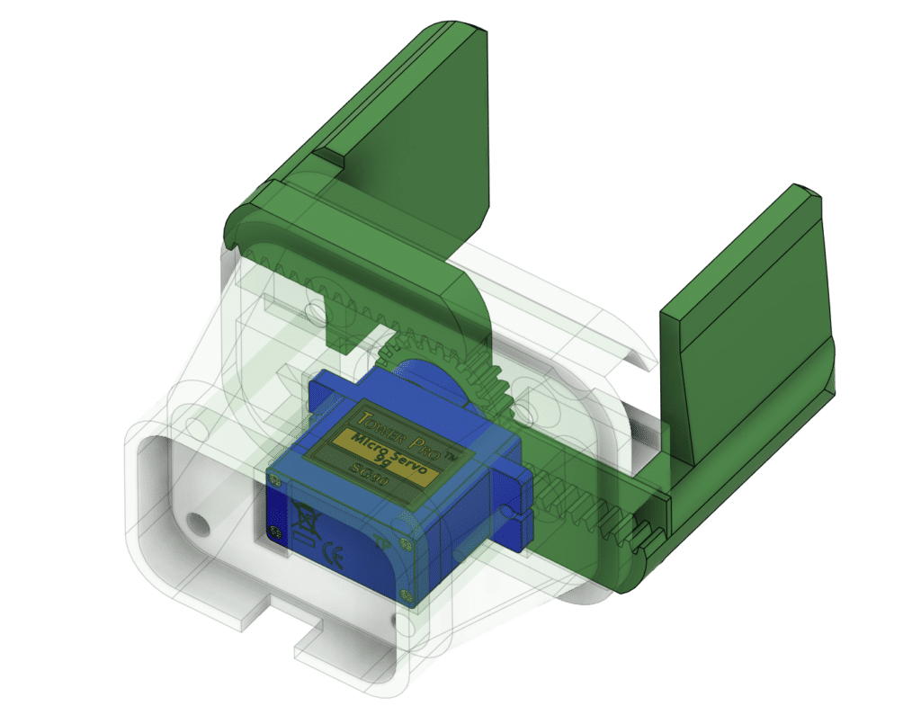
I initially provided two T-slots for the finger slide track. Combined with the rack and pinion gear, I get the following profile for the gripper. The flanks of the slots and the gearwheel partly support the fingers. The tests carried out show that this works flawlessly. I placed the servo itself completely inside the housing of the gripper.
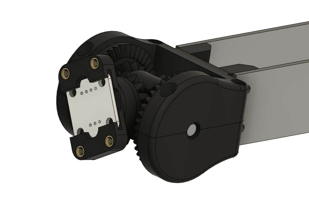
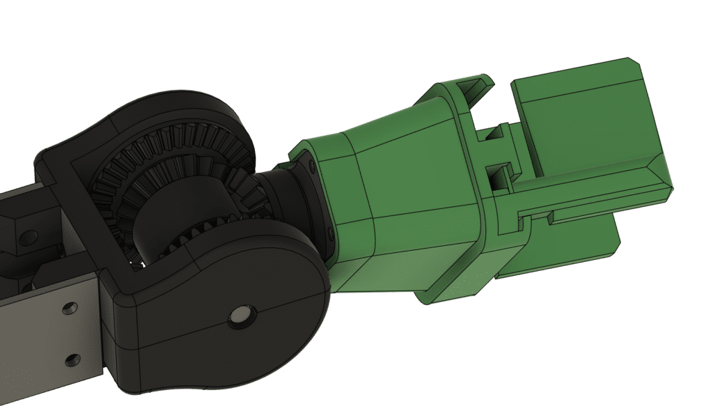
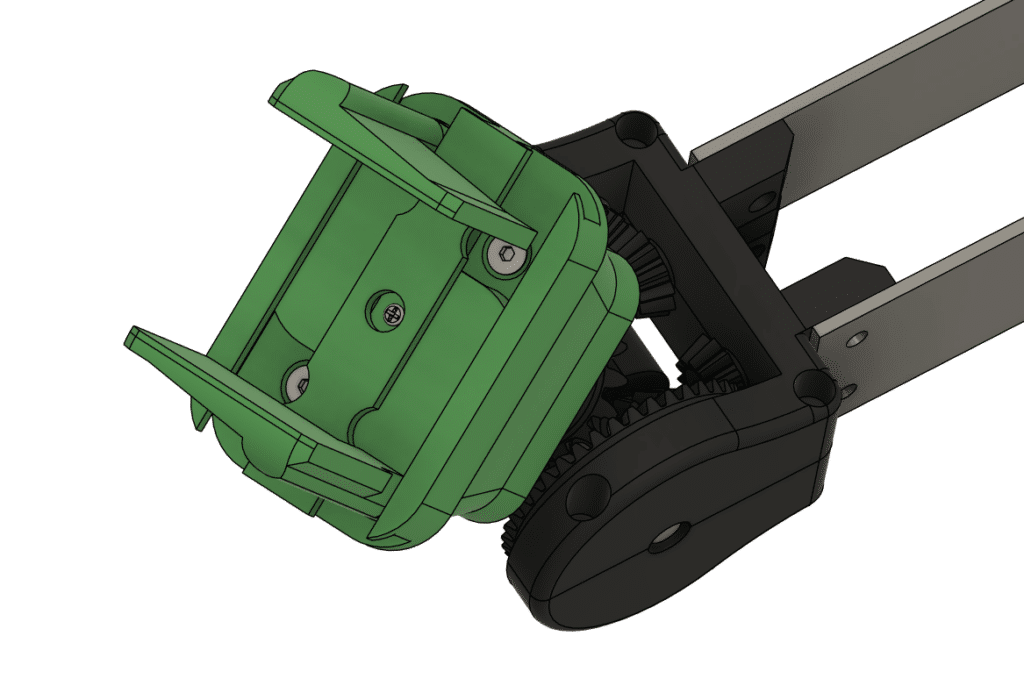
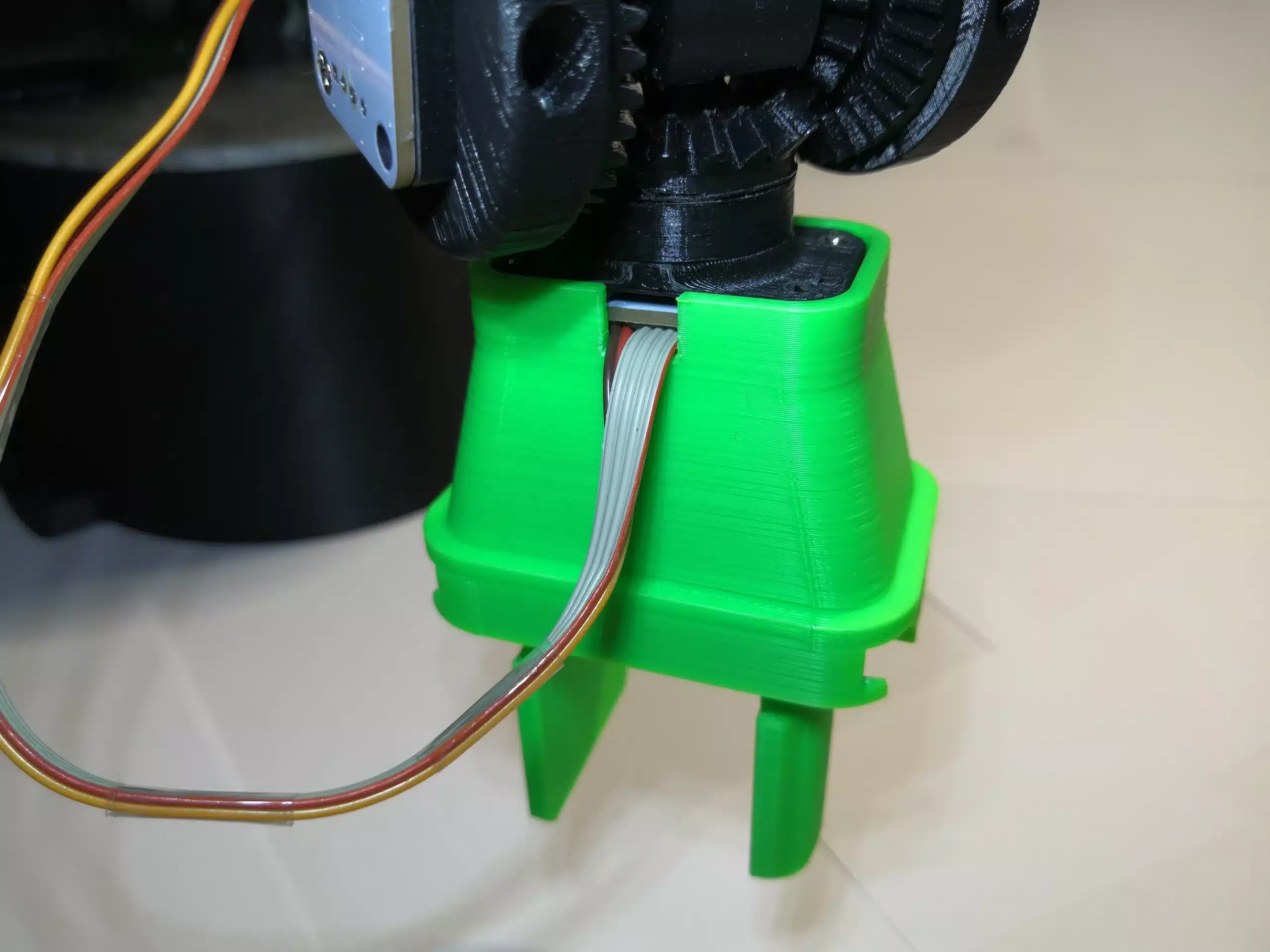
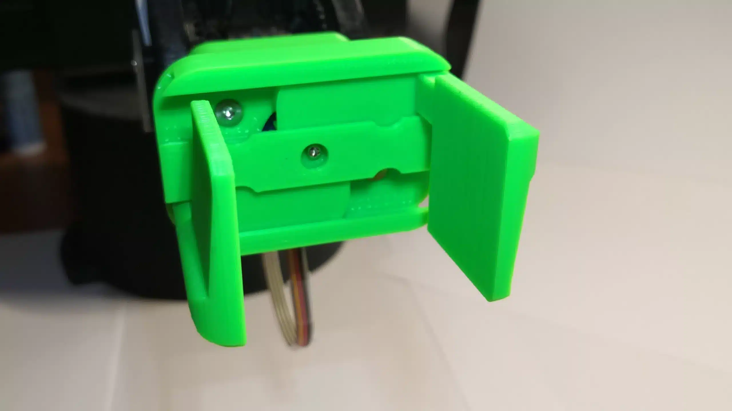
The flange to the robot’s wrist consists of four M3 internal threads. You can see it in the following image. The white circuit board contains an angle sensor that detects the current configuration of the robot’s last axis. I adapted the housing of the gripper to the flange so that it also completely encloses the angle sensor. Four M3x35mm countersunk screws attach the gripper to the wrist.
3D Printed Result
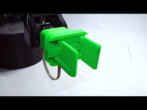
I printed the gripper with PLA+ on my 3D printer Artillery Sidewinder X2* with 20% infill and a layer height of 0.2mm. Below are some photos of the gripper and a video of the gripper in action.
By viewing the video, you agree that your data will be transmitted to YouTube and that you have read the privacy policy
CAD Files
You can download all CAD files as STEP and STL files from GrabCAD: Micro Servo Parallel Gripper | 3D CAD Model Library | GrabCAD
* The links are affiliate links. The offers do not come from me. However, I receive a commission through the reference if a purchase takes place, but without you incurring additional costs.
4 Comments
Diema1 · 01/05/2024 at 4:33
Cómo realizo este diseño para un servo mg996 que tenga una abertura entre pinzas de más de 12cm??
Techniccontroller · 01/05/2024 at 20:14
Hello Diemal,
thank you for your comment. If you are using a larger servo like the MG996 you need to redesign the CAD model so that the servo can fit inside. Also if you want to open the gripper 12cm you need to design a larger spur gear. In my current design, the spur gear has a diameter of 15mm which allows me to open the gripper 47mm when the servo rotates 180°.
15mm * PI * 180°/360° * 2 = 15mm * PI = 47mm
If the maximum gripper opening should be 120mm then the diameter of the spur gear needs to be 39 mm:
120 mm / PI = 39mm
You can simply scale my model by a factor of 39/15=2,6. You just need to adjust the servo mounting afterwards, because your servo is not scaled with the same factor.
I have provided the STEP file of my gripper, so it should be possible for you to design your version of the gripper.
Best regards
Edgar
Diema · 11/05/2024 at 1:29
Gracias por la indicación, intentaré realizar el nuevo diseño, que libro o tutoriales me recomienda para aprender sobre este tipo de mecanismos?
Techniccontroller · 12/05/2024 at 8:20
Hi Diema,
I came up with this gripper design mainly by myself. I don’t know which book or tutorial you need or expect. It may be useful for you to search for “rack and pinion drives”.
Best regards
Edgar