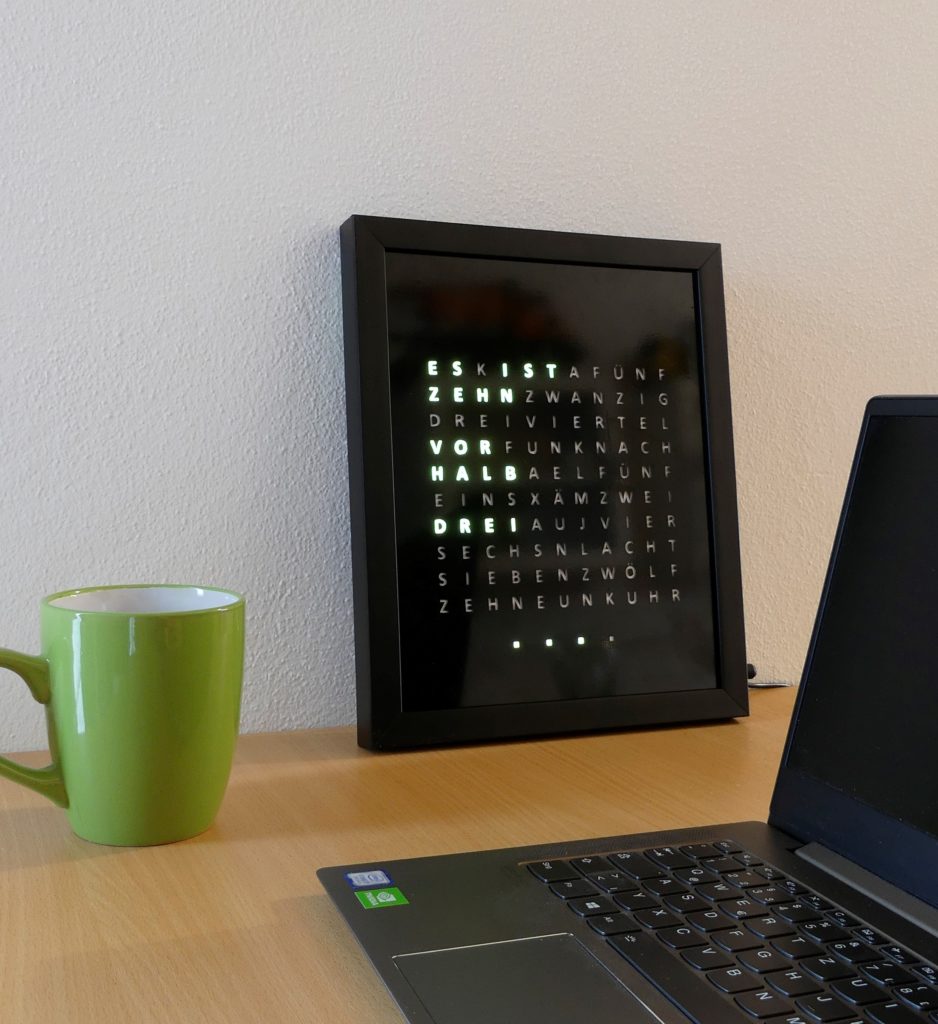
In this post, I will build a super cool word clock with Arduino and Neopixel LEDs. Such word clocks cost several hundred euros in the trade, but with a little skill, they are also fast self-built. I show you how it works. The electronic base is similar to that of my LED-Matrix.
UPDATE 2022: I built version 2.0 of the Word clock. This time with WiFi and some games to play on it (Pong, Tetris, Snake). Find my blog post about it here.
Material for the word clock
You need the following material for the word clock. Overall they cost less than 100 EURO.
- deep wooden picture frame 24x30cm (or similar size, amazon.de*)
- black adhesive foil (amazon.de*)
- NeoPixel LED Strip with 114x WS2812b LEDs (60LEDs/m) (amazon.de*)
- Arduino Nano V3.0 (amazon.de*)
- Real-Time-Clock Modul DS3231 (amazon.de*)
- power supply 5V/3A (amazon.de*)
- DC power jack 5.5×2.1 (amazon.de*)
- two sheets of black cardboard
- one sheet of white paper
- some cables, one 470 Ohm resistor, one 1000uF capacitor, one small switch
Optionally you can upgrade the Word Clock with these components:
- DCF77 Receiver Module (amazon.de*)
- LDR light sensor module LM393 (amazon.de*)
- rocker switch as on/off switch (in the power supply lines) (amazon.de*)
- breadboard PCB (amazon.de*)
* The links are affiliate links. The offers do not come from me, however, I receive a commission through the reference, if then a purchase takes place, but without you incurring additional costs.
Step-by-Step instructions
- The first step is to stick the adhesive foils onto the glass pane of the picture frame. Tip: Here it helps to spray the glass pane with detergent water first so that the bubbles can be easily pushed out of the foil afterward.
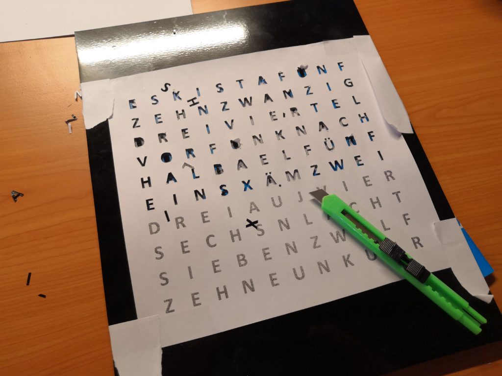
- The most complex task is cutting out the individual letters from the black adhesive foil. The best way to do this is to print out a template with the letters and fix it on the glass pane with adhesive tape. Now the letters can be cut out with a sharp cutter knife.
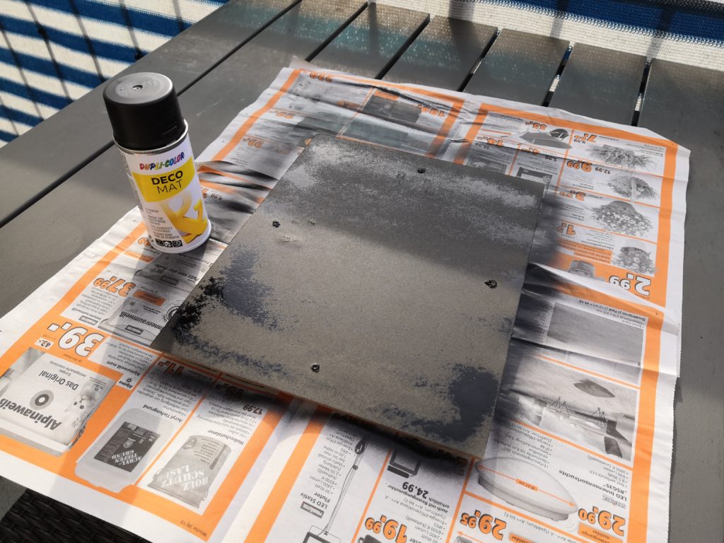
- To avoid reflections, it is recommended to paint the back panel with spray paint.
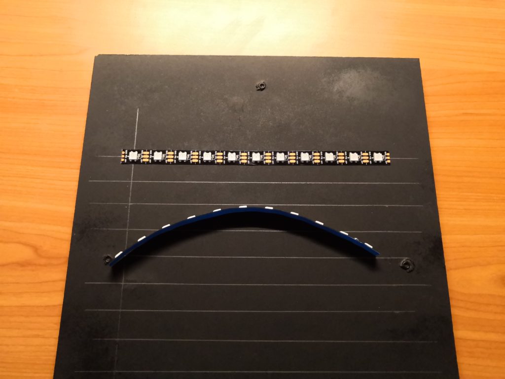
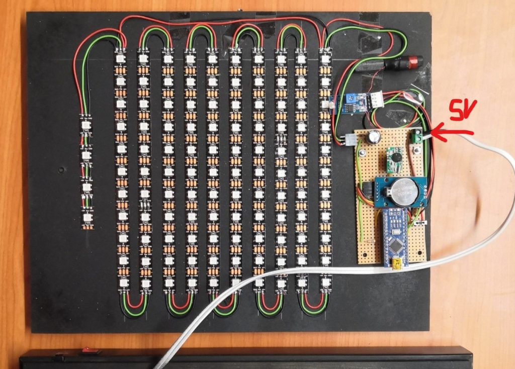
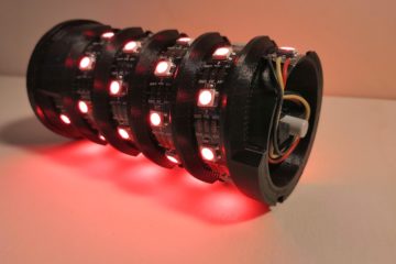
- Now you divide the LED strip into 10 strips of 11 LEDs each and glue them in a zigzag pattern on the back of the picture frame. It helps to mark the desired position on the back panel.
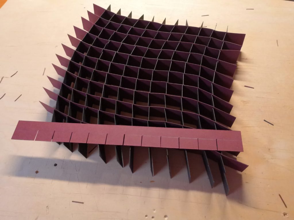
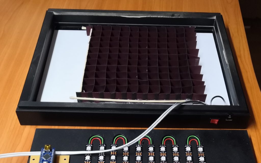
- To reduce stray light from the individual LEDs, we now create a grid structure from the black cardboard. To do this, we cut 2 cm wide strips from the cardboard and cut them 11 or 12 times up to the middle. Afterward, the strips can be put together as grids as shown in the picture below.
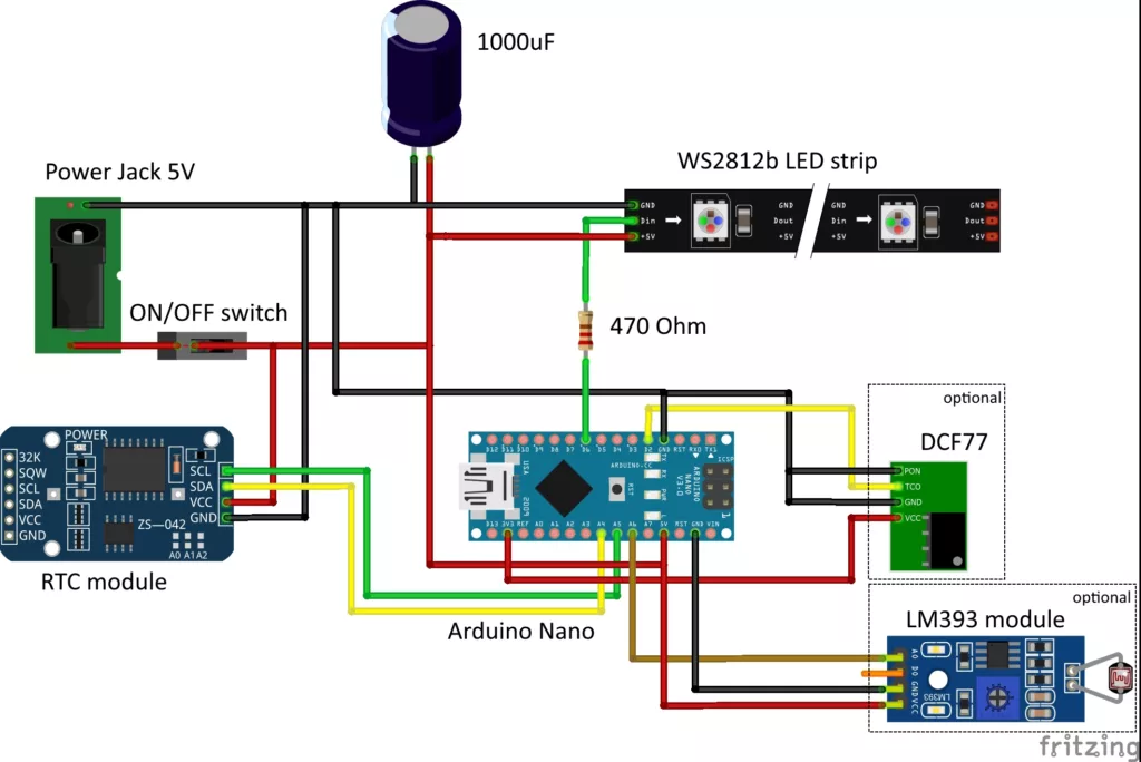
- Now it goes to the electronics. We solder the Arduino with the LED strips and the real-time clock (RTC) module. It doesn’t matter if you use a hole board or solder the cables directly. As an add-on, you can add the radio clock receiver module DCF77 and/or the light sensor module for automatic brightness control, but this is not absolutely necessary. The RTC module with its battery always keeps the current time. But without using the radio receiver you have to flash the Arduino again when changing the battery of the RTC module.
techniccontroller / think_wordclock
Arduino source code for the Wordclock on GitHub
- The next step is to flash the software to the Arduino. The complete source code can be found here on GitHub. It also describes which additional libraries need to be installed in the Arduino IDE. While connecting to a computer via USB, the small switch must be turned off (to prevent damage to the Arduino due to the high current drawn by the LEDs).
- So that the letters shine as a whole and not the individual LEDs are visible, we now stick a simple sheet of white paper on the back of the glass plate. Then we fix the grid with hot glue on the glass plate.
- The last step is to insert the glass plate and back panel into the picture frame. You can also add an on/off switch in the picture frame.
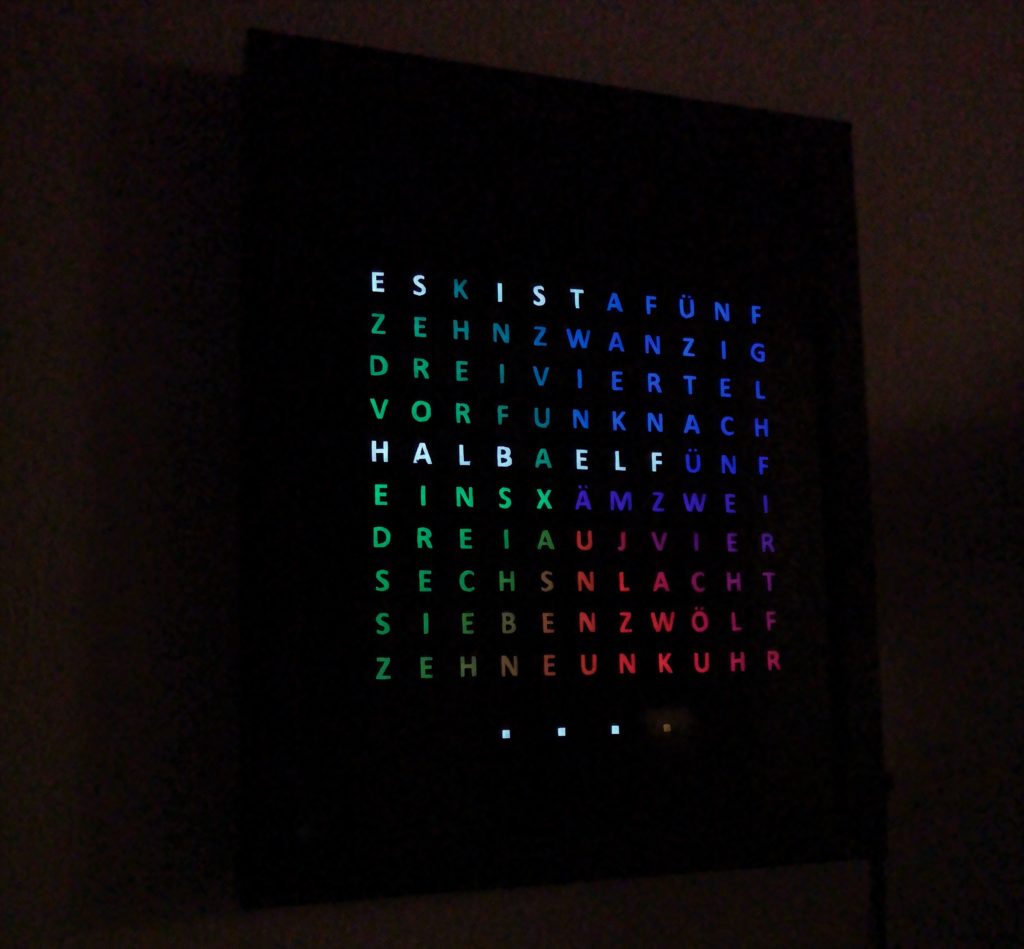
You can extend the project as desired: As some of you might have noticed in the pictures above, a built-in light sensor allows automatic adjustment of the brightness of the LEDs to the environment. I placed the light sensor inside the first “K” and connect it to an analogue input (A6) of the Arduino.
Have fun rebuilding it.
96 Comments
Thomas · 06/09/2022 at 20:15
Hallo Edgar
Supertolles Projekt! Version 1 ist schon am laufen, Verrsion 2 noch nicht – bin leider auch kein Arduinoprofi 😉
Bei der Wordclock V2 bleibt Arduino bei
‘Base64’ was not declared in this scope; did you mean ‘base64’?
hängen, vielleicht kannst du mir helfen?
VG
Thomas
Techniccontroller · 06/09/2022 at 21:45
EDIT 17.09.2022:
Hallo Thomas,
thank you for your comment
There was an issue with the library configuration on my computer. I have now included the Base64 library in the GitHub Repo. Please check again the GitHub repo and copy the two files (Base64.h, Base64.cpp) next to the wordclock_esp8266.ino file. Also change the #include statement in the wordclock_esp8266.ino file
from
#include
to
#include “Base64.h”
BR
Edgar
Nicklas · 04/09/2022 at 11:49
Hallo,
kann man den Code auch ohne den DCF benutzen? Wenn ja, was muss ich am Code ändern?
Techniccontroller · 04/09/2022 at 18:27
Hallo Nicklas,
danke für dein Interesse an dem Projekt. Eigentlich musst du an meinem originalen Code nichts ändern. Wenn kein DCF angeschlossen ist, wird er auch nicht verwendet und dessen Funktion ignoriert. Sollte also laufen auch ohne DCF.
Aber bevor du meinen Code laufen lässt ist es sinnvoll zunächst mit einem kleinen Testprogramm zu prüfen ob alle LEDs und die RTC funktionieren.
Im Anschluss kann man meine Programm probieren, ob es funktioniert, und wenn nötig via Serialport (USB) debuggen.
Wenn du weitere Fragen hast, gerne melden.
VG Edgar
(Deinen geposteten Code werde ich hier in den Kommentaren der Übersicht wegen löschen.)
Nicklas · 30/09/2022 at 11:53
Hallo,
Danke für deine schnelle Antwort. Ich habe nun nach einer kurzen Pause wieder angefangen am Projekt zu arbeiten. Ich habe den Code jetzt in original Form gelassen und habe den DCF nicht angeschlossen. Wenn ich versuche, den Code hochzuladen bekomme ich den gleichen Fehler wie Sandy(25/10/2021 um 20:03). Ich habe die gesamte Datei von Github runtergeladen, aber der Fehler bleibt. Was kann ich machen? Und wo finde ich das Testprogramm, um alle LEDs und den RTC zu testen?
Grüße
Nicklas
Nicklas · 30/09/2022 at 14:04
Hallo Nochmal,
Nach weiteren versuchen hat es funktioniert. Vielen Dank! Eine Frage noch: ist es möglich, sie per E-Mail zu kontaktieren? Ich habe selbst Interesse daran bei der TUM zu studieren und habe ein paar Fragen, die ich einem Schüler an der Uni fragen möchte. Vielen Dank.
Grüße
Nicklas
Tobias · 31/03/2022 at 17:35
Hallo Edgar,
super geiles Projekt mit entsprechender Anleitung. Bin gerade am Zusammensuchen der Teile. Dabei ist mir folgendes aufgefallen:
In der Stückliste ist ein Widerstand mit 470 Ohm angegeben, im Schaltplan (Punkt 6) einer mit 220 Ohm. Was ist richtig?
Noch eine Frage zur Größe:
Du hast hier die Streifen der LEDs Zeilenweise zusammen gelassen, dadurch ist die Größe 24×30 cm zustande gekommen. Wenn man die LED-Streifen auf trennt und mit Aderstücken wieder zusammenlötet um einen größeren Bilderrahmen zu füllen, z.B. 50 x 50 cm, reicht die Helligkeit der LEDs für die größeren Buchstabenfelder noch aus?
Grüße Tobias
Techniccontroller · 31/03/2022 at 22:44
Hallo Tobias,
danke für deinen Kommentar. Da ist tatsächlich ein Fehler im Bild, 470Ohm ist die empfohlene Größe des Widerstands. Werde ich gleich korrigieren :).
Bezüglich der Größe der Wortuhr würde ich an deiner Stelle einen LED Streifen mit 30 LEDs/Meter (statt 60LEDs/Meter) nehmen, damit hast du auch den größeren Abstand und musst nicht so viel löten. Hat bei mir gut funktioniert (siehe meine Wortuhr 2.0, welche ebenfalls die Größe von 50x50cm hat: https://techniccontroller.de/word-clock-with-wifi-and-neopixel/).
Die Helligkeit reicht vollkommen aus. Anstatt des normalen weißen Papiers habe ich allerdings weißes Backpapier verwendet und das Lichtgitter mit Spiegelfarbe bemalt (statt schwarz). Das hat vielleicht etwas geholfen, aber es würde sicher auch ohne gehen.
Viel Spaß beim Nachbauen der Uhr.
VG Edgar
Tobias · 02/04/2022 at 23:36
Hallo Edgar,
danke für die schnelle Antwort.
Ich habe mir dein Wordclock 2.0 Projekt natürlich auch gleich angeschaut und bin begeistert.
Für den Anfang werde ich aber wohl doch die Uhr hier mit Funkempfänger hier ausprobieren und nicht mit NTP Server.
Kannst du mir sagen wo genau ich den Helligkeitssensor anschließen muss? Das ist nicht in der Schematic enthalten und auf dem Foto leider nicht zu erkennen.
Danke schonmal
Gruß Tobias
Tobias · 03/04/2022 at 12:29
Hab es im Code gefunden : A6.
Techniccontroller · 03/04/2022 at 14:17
Ja genau, den Sensor hatte ich nicht nochmal explizit in den Schaltplan eingezeichnet.
Tobias · 16/04/2022 at 23:05
Hallo Edgar,
ich muss mich nochmal an dich wenden. Der Nightmode schein bei mir nicht zu funktionieren. Die Uhr leuchtet dauerhaft durch, auch in der Nacht. Im Code steht ja foldendes:
// convert time to a grid representation
timeToArray(rtctime.hour(), rtctime.minute());
// clear matrix
matrix.fillScreen(0);
// add condition if nightmode (LEDs = OFF) should be activated
if(rtctime.hour() > 22 && rtctime.hour() < 6){ // turn in off LEDs between 22:00 and 6:00
// do nothing, matrix already cleared (see previous statment)
} else {
// do the normal job and display the time on the wordclock
muss ich hier noch an irgend einer Stelle irgendwas aktivieren oder löschen? Direkt davor wird ja die Uhrzeit auf das Array geschrieben. Kann das die Ursache sein?
Grüße
Tobias
Techniccontroller · 16/04/2022 at 23:34
Hallo Tobias,
Das ist tatsächlich seltsam, eigentlich sollte das klappen. Ich hatte das Feature vor einem halben Jahr für jemanden implementiert (leider blind, da ich die Uhr damals nicht zur Hand hatte). Hat damals scheinbar funktioniert und ich sehe aktuell auch den Fehler im Code nicht. Erst der Befehl drawOnMatrix() überträgt die Daten aus dem grid auf die Matrix. Und der Befehl wird ja durch die Bedingung übersprungen.
Ich kann mich morgen nochmal dran setzen und es auf meiner Uhr ausprobieren.
VG
Edgar
Techniccontroller · 17/04/2022 at 20:08
Ich hab den Fehler gefunden: die Bedingung für den Nightmode war falsch. Der Code muss so aussehen:
  // add condition if nightmode (LEDs = OFF) should be activated
  // turn off LEDs between NIGHTMODE_START and NIGHTMODE_END
  uint8_t nightmode = false;
  if(NIGHTMODE_START > NIGHTMODE_END && (rtctime.hour() >= NIGHTMODE_START || rtctime.hour() < NIGHTMODE_END)){
    // nightmode duration over night (e.g. 22:00 -> 6:00)
    nightmode = true;
  }
  else if(NIGHTMODE_START < NIGHTMODE_END && (rtctime.hour() >= NIGHTMODE_START && rtctime.hour() < NIGHTMODE_END)){
    // nightmode duration during day (e.g. 18:00 -> 23:00)
    nightmode = true;
  }
Der vollständige Code ist wie immer auf GitHub:
https://github.com/techniccontroller/think_wordclock
Luegenwalder · 24/01/2022 at 14:14
Moin,
das ist echt ein geiles Projekt und ich bin grade dabei es nach zu machen.
Leider habe ich ein Problem beim Kompilieren.
Folgender Fehler wird ausgegeben.
In file included from C:\Program Files (x86)\Arduino\libraries\Adafruit_GFX_Library\Adafruit_GrayOLED.cpp:20:0:
C:\Program Files (x86)\Arduino\libraries\Adafruit_GFX_Library\Adafruit_GrayOLED.h:30:10: fatal error: Adafruit_I2CDevice.h: No such file or directory
#include
^~~~~~~~~~~~~~~~~~~~~~
compilation terminated.
exit status 1
Fehler beim Kompilieren für das Board Arduino Nano.
Bin leider kein Experte im programmieren.
Würde mich freuen wenn Sie mir helfen könnten.
Freundliche Grüße
Techniccontroller · 24/01/2022 at 22:15
Hallo,
kann es sein, dass Sie eine ältere Arduino IDE version nutzen?
Es wurde scheinbar eine fehlenden Arduino Bibliothek nicht automatisch mit der Adafruit_GFX-Library mit installiert.
Bitte mal versuchen diese Bibliothek noch zu installieren: https://github.com/adafruit/Adafruit_BusIO
Diese sollte die fehlende Datei beinhalten.
Vielen Grüße
Edgar
Dieter · 26/11/2021 at 2:55
Hallo zusammen!
Cooles Projekt, bin gerade dabei, es nachzumachen.
Dabei stellt sich mir die Frage:
Für was benötigt ihr den 12 V Anschluss?
Der Arduino braucht ja 5 V und die LEDs werden ja auch nur mit 5V versorgt oder?
Vielen Dank schonmal!
Liebe Grüße
Techniccontroller · 26/11/2021 at 9:32
Hallo Dieter,
danke für den Hinweis, du hast einen Fehler entdeckt :).
Natürlich sind das nur 5V als Versorgungsspannung, wie ich es auch in der Komponentenliste am Anfang des Artikels geschrieben habe. Ich habe das Bild mit den 12V nun korrigiert.
Viel Spaß beim Nachbauen.
Vielen Dank
VG
Edgar