I have the situation that I use a Raspberry Pi without a screen and other peripheries attached. It should work as Wi-Fi hotspot with a small web server on. To prevent the emergence of a corrupt SD card, I was looking for a solution to safely shutdown the Raspberry Pi simply by disconnecting the power supply.
In the following tutorial, I will show you how to build a small UPS (uninterruptible power supply) for your Raspberry Pi Zero for less than 10 Euro. The UPS will automatically trigger a safe shutdown when the power supply is disconnected.
STEP 1: Items you will need
You need the following components for the MiniUPS:
1x Adafruit Perma Proto Bonnet Mini Kit | 6,00 € |
2x Super Capacitor 10F 2.7V | 1,40 € |
1x TL7705BCP Supply-Voltage Supervisor | 1,00 € |
1x Micro USB To DIP Adapter | 0,25 € |
1x BC547 NPN Bipolar Transistor | 0,20 € |
1x 2SJ438 P-Channel MOSFET Transistor | 0,50 € |
2x Ceramic 0.1uF Capacitor | 0,20 € |
Resistors (2x 10k, 2x 4k7, 1x 1k, 2x 100) | ~0,10 € |
some wires | |
| Total | 9,60 Euro |
Additional you need the following tools:
- Soldering Iron
- Solder
- Electric pliers
- Cutter knife
STEP 2: Explaining the circuit
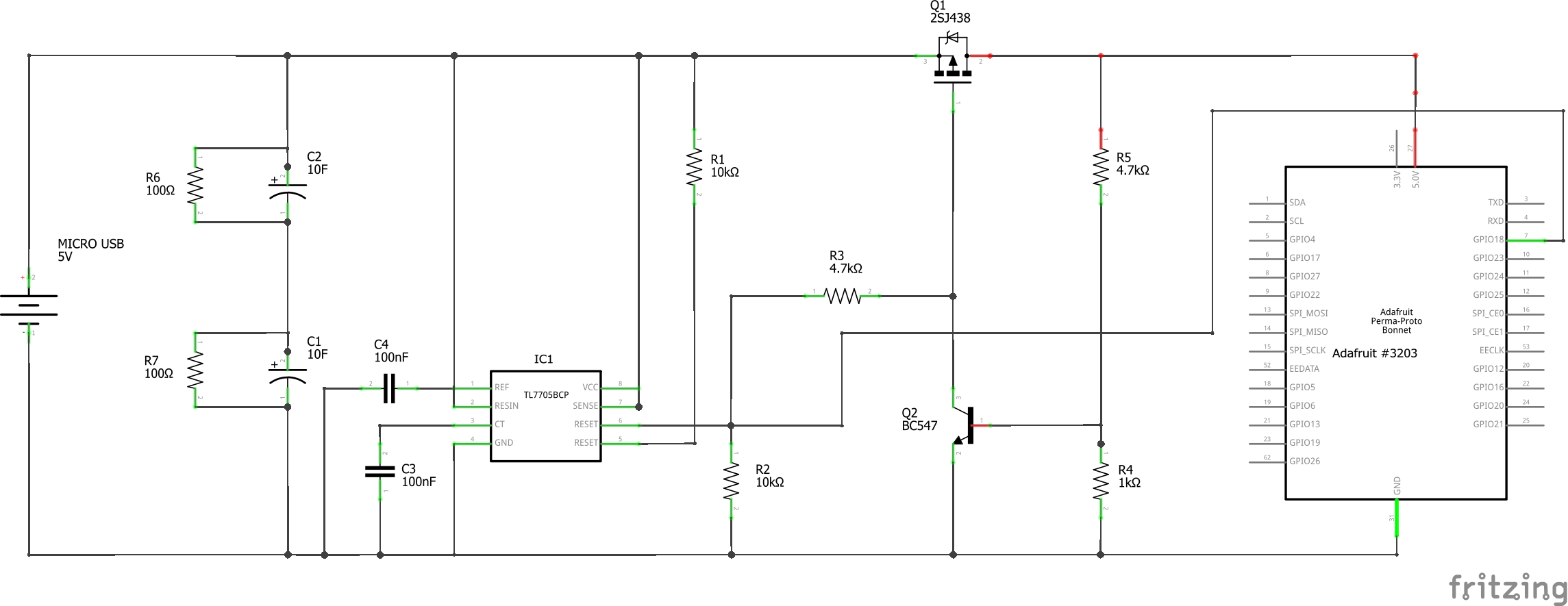
Picture 1: complete circuit of the MiniUPS
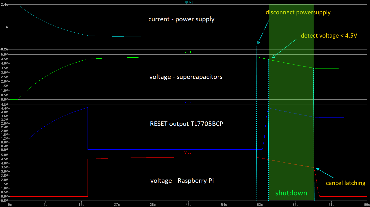
I use supercapacitors to buffer the voltage until the Raspberry Pi shuts down. The safe shutdown is triggered by a TL7705BCP supply-voltage supervisor, which turns its RESET output HIGH at a voltage below 4.5V. A small script runs on the Raspberry Pi in the background to start the shutdown on a rising edge on a GPIO pin.
Since charging the supercapacitors takes a few seconds and leads to a slowly rising voltage, some USB devices have problems on startup. We, therefore, insert an automatic switch, which we use to supply the Raspberry Pi with voltage only when the voltage has reached a value of 4.5V. Here again, we use the RESET output of the voltage supervisor to switch on the MOSFET transistor only from a voltage of 4.5V.
However, so that the MOSFET does not block directly at low voltage, we implement latching of the MOSFET with the bipolar transistor BC547B. Only when the voltage has fallen below a value of about 3.4 V, the MOSFET disconnects the supply voltage of the Raspberry Pi.
This time between 4.5V and 3.4V is usually enough to shut down the Raspberry Pi. Only if large consumers (e.g. a monitor) are powered via USB from the Raspberry Pi it could be scarce, here it could help to increase the supercapacitors to 20F.
To simplify handling, I build the circuit on a prototype board from Adafruit and add a micro USB to DIP adapter.
I have the circuit in advance with LTSpice simulated. Here you can download my model of the circuit: MiniUPS_Simulation_LTSpice.asc
STEP 3: Prepare the prototype board
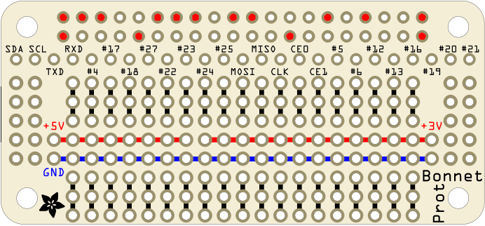
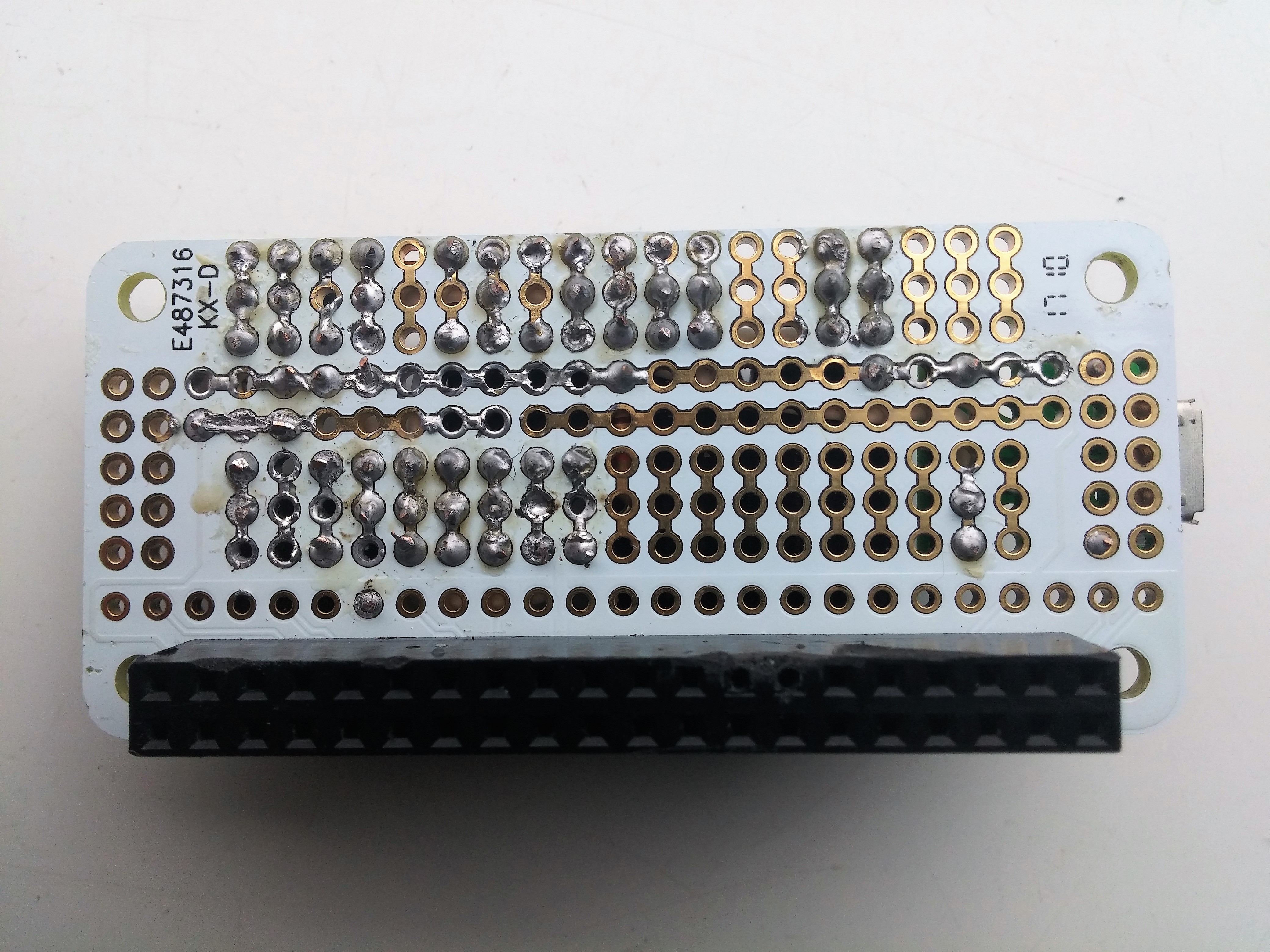
First, we need to solder the header to the prototype board, but we only need a few pins, so I’ve just soldered these to the board:
STEP 4: Wires
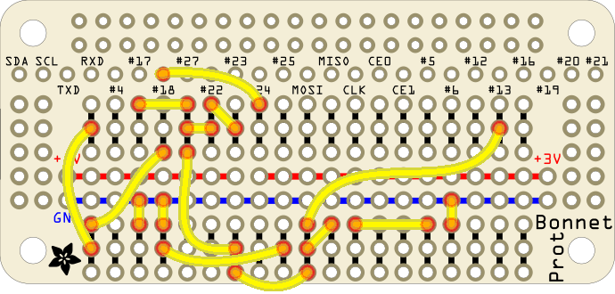
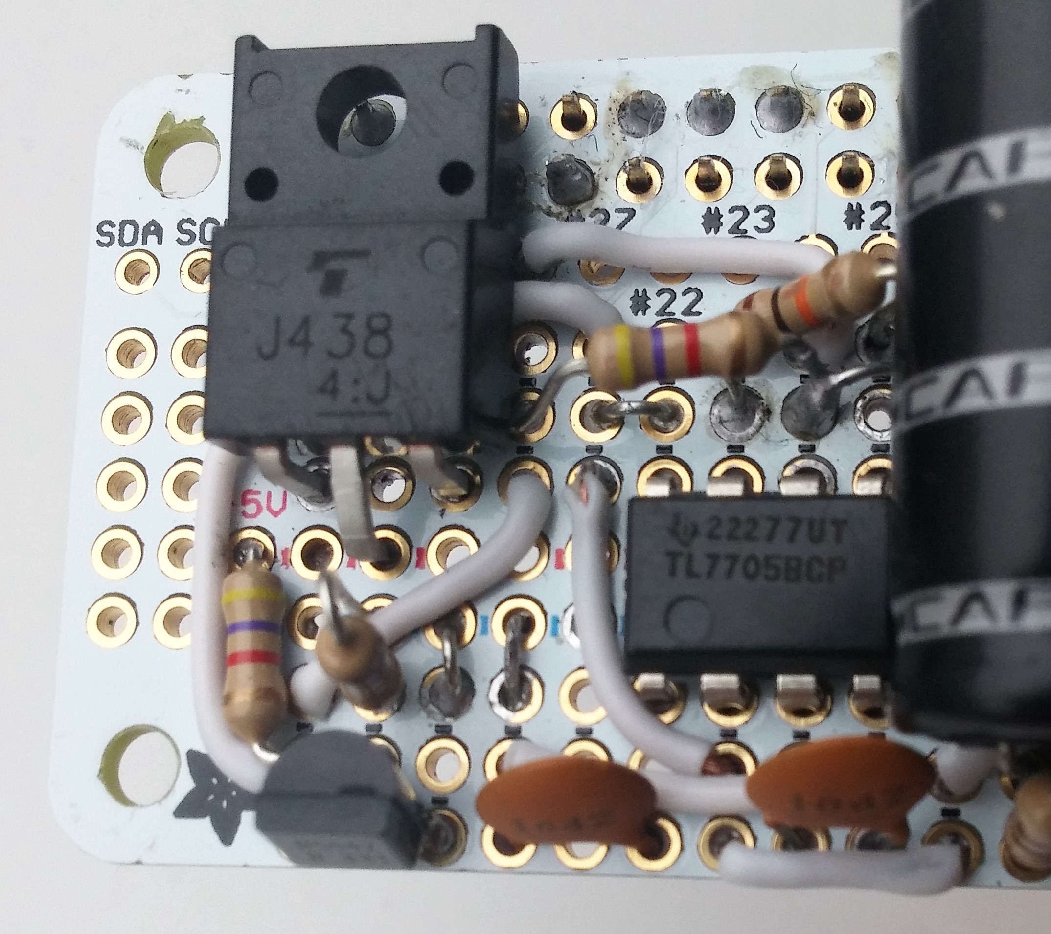
Solder the wires as shown in the picture below
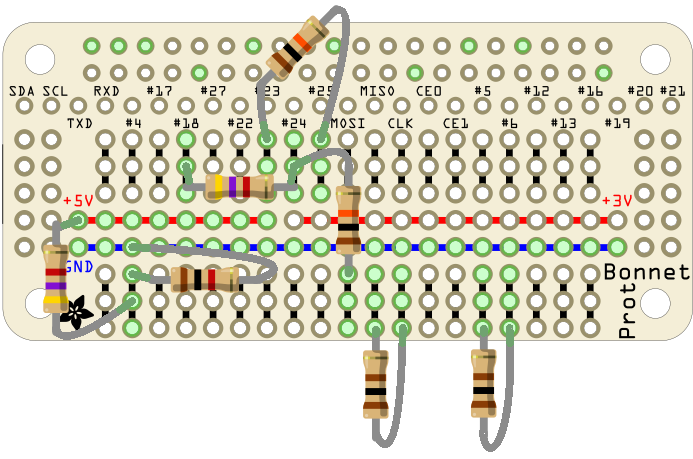
STEP 5: Resistors
Place the resistors as shown in the picture below:
STEP 6: Other Parts
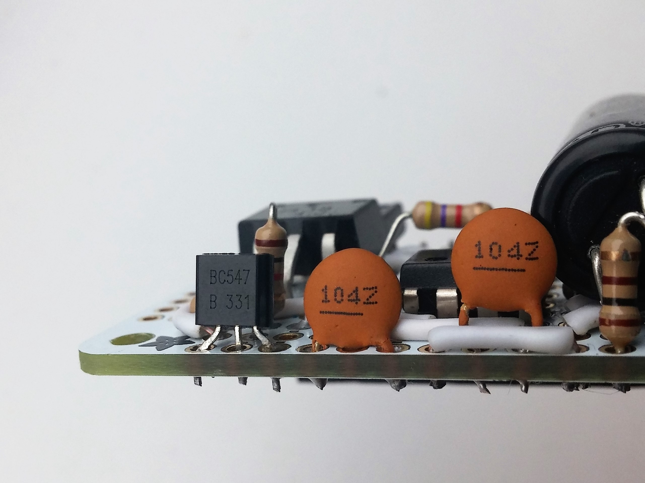
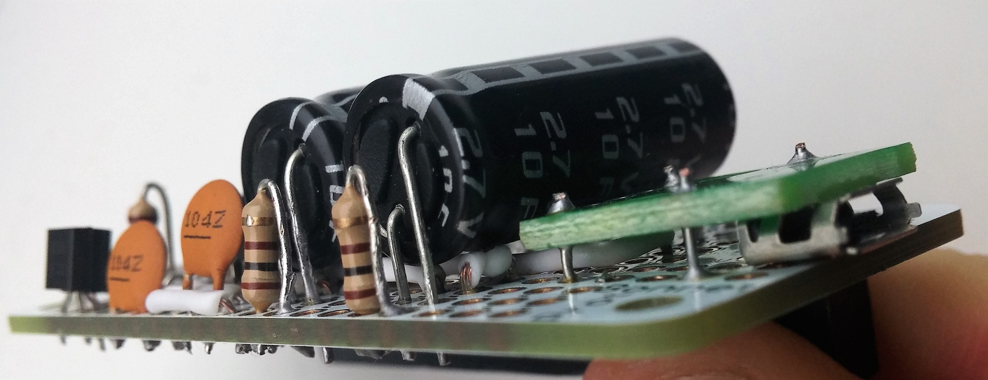
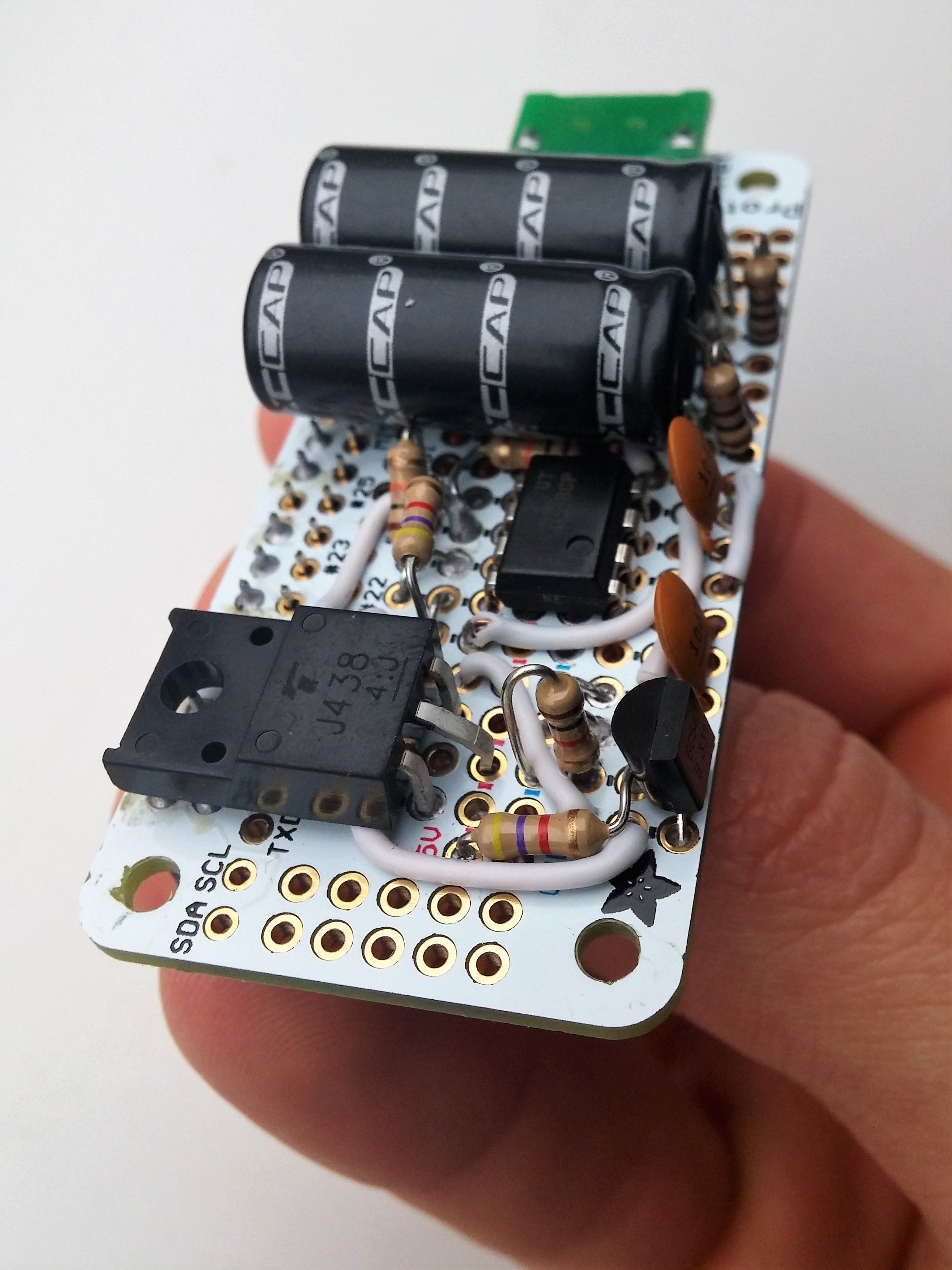
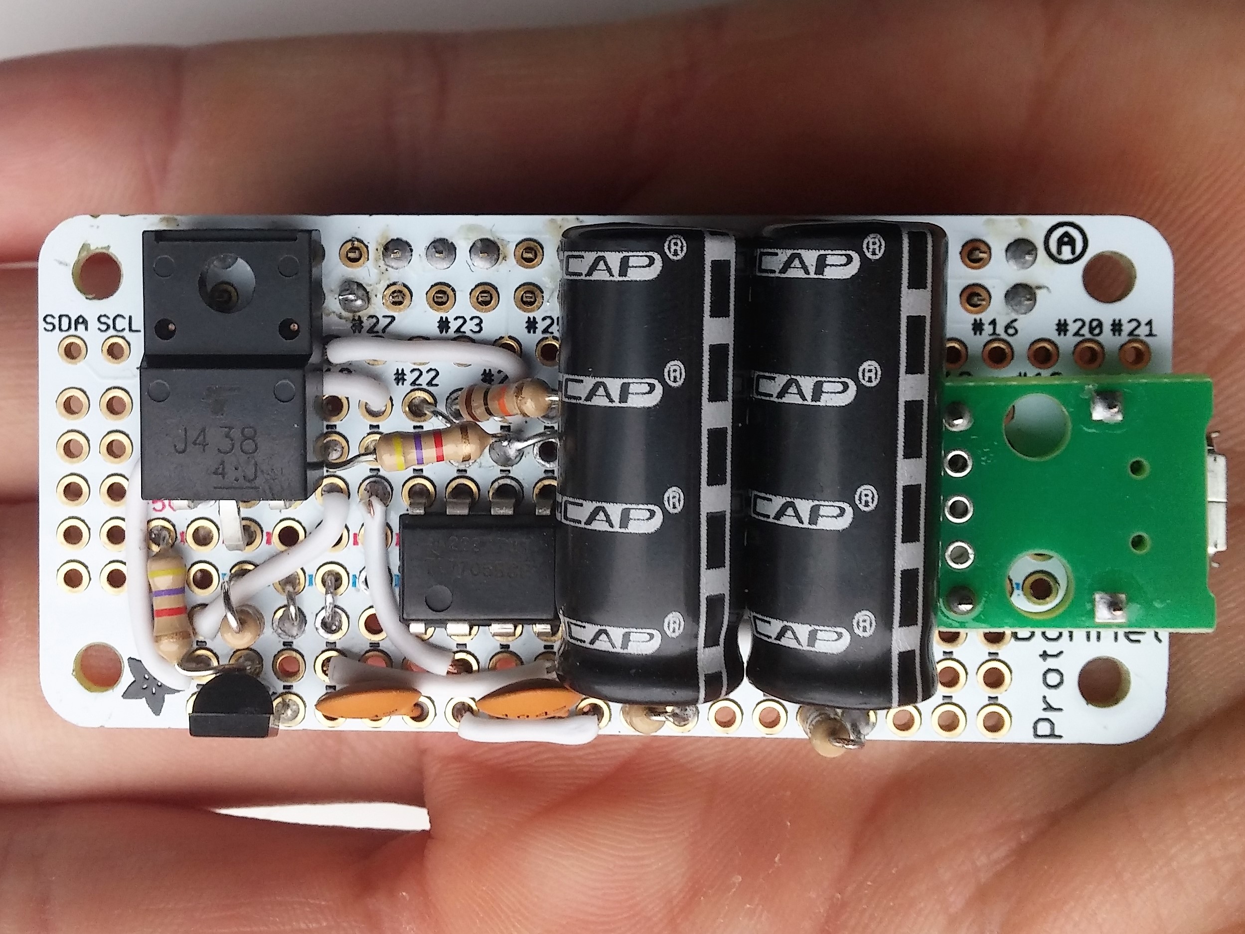
Now you can add the larger parts:
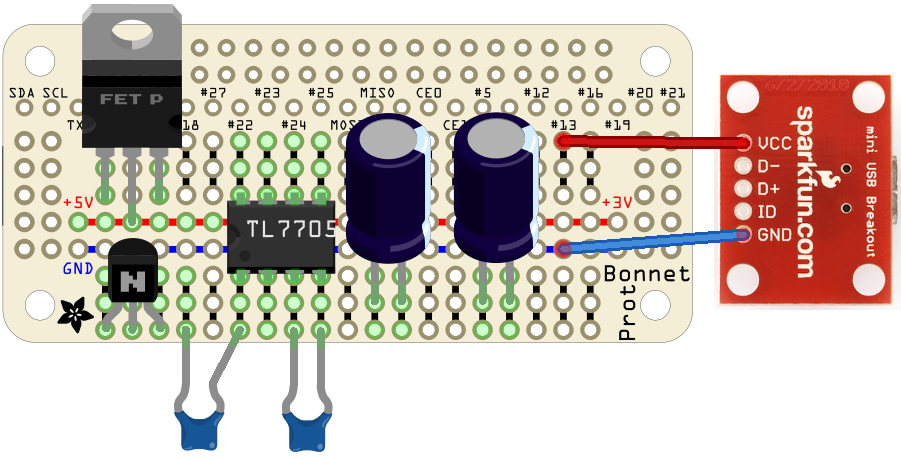
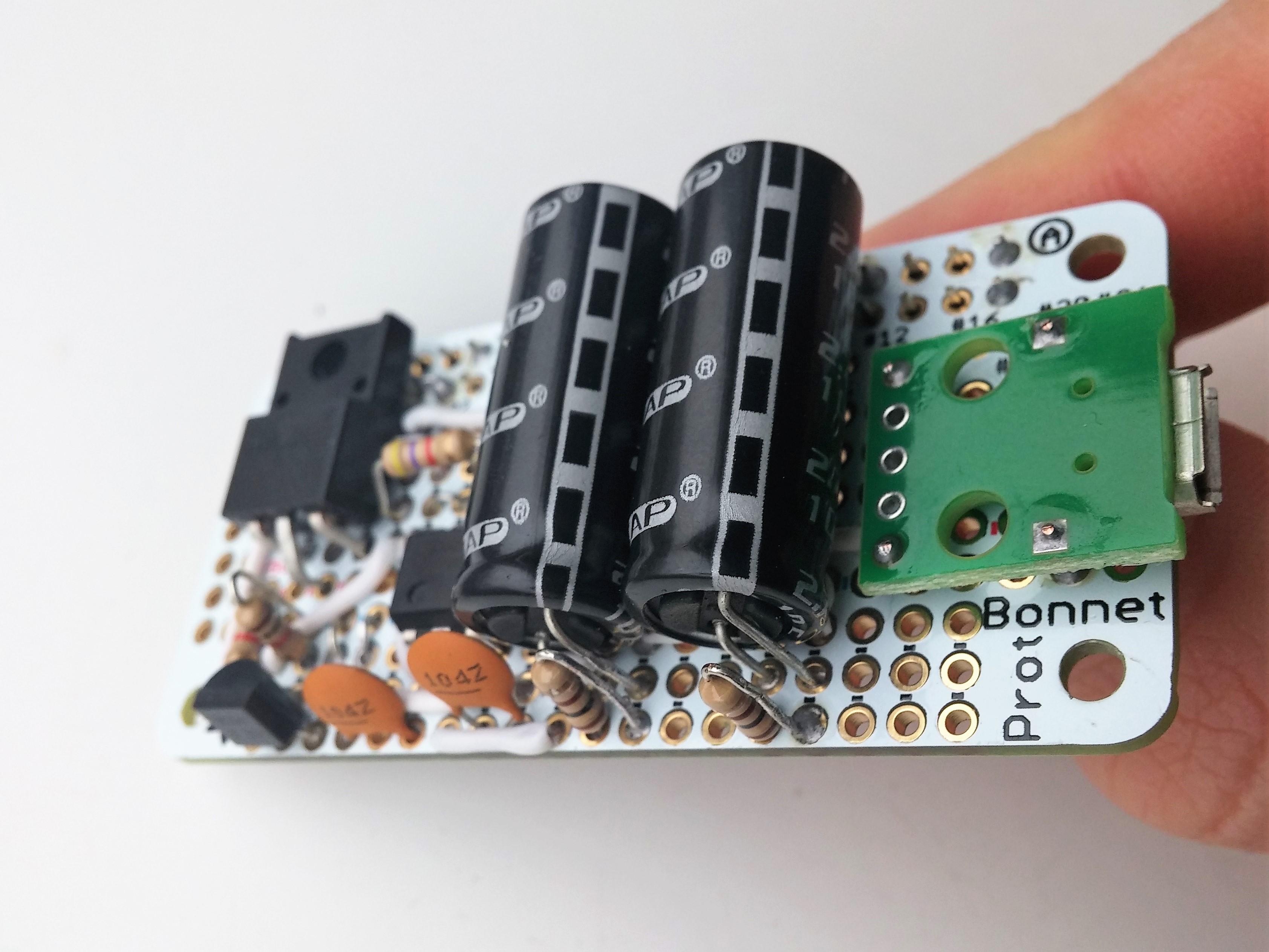
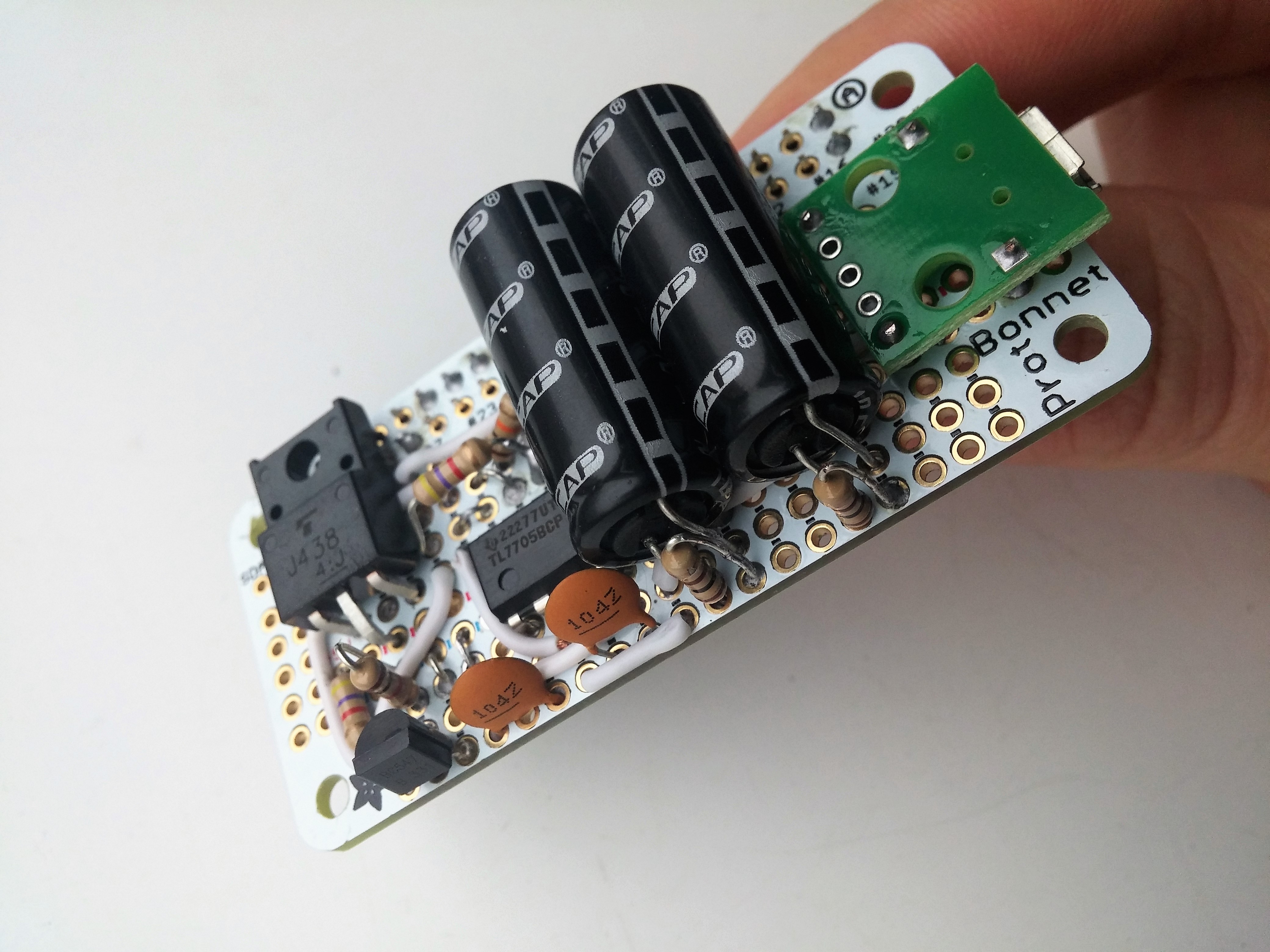
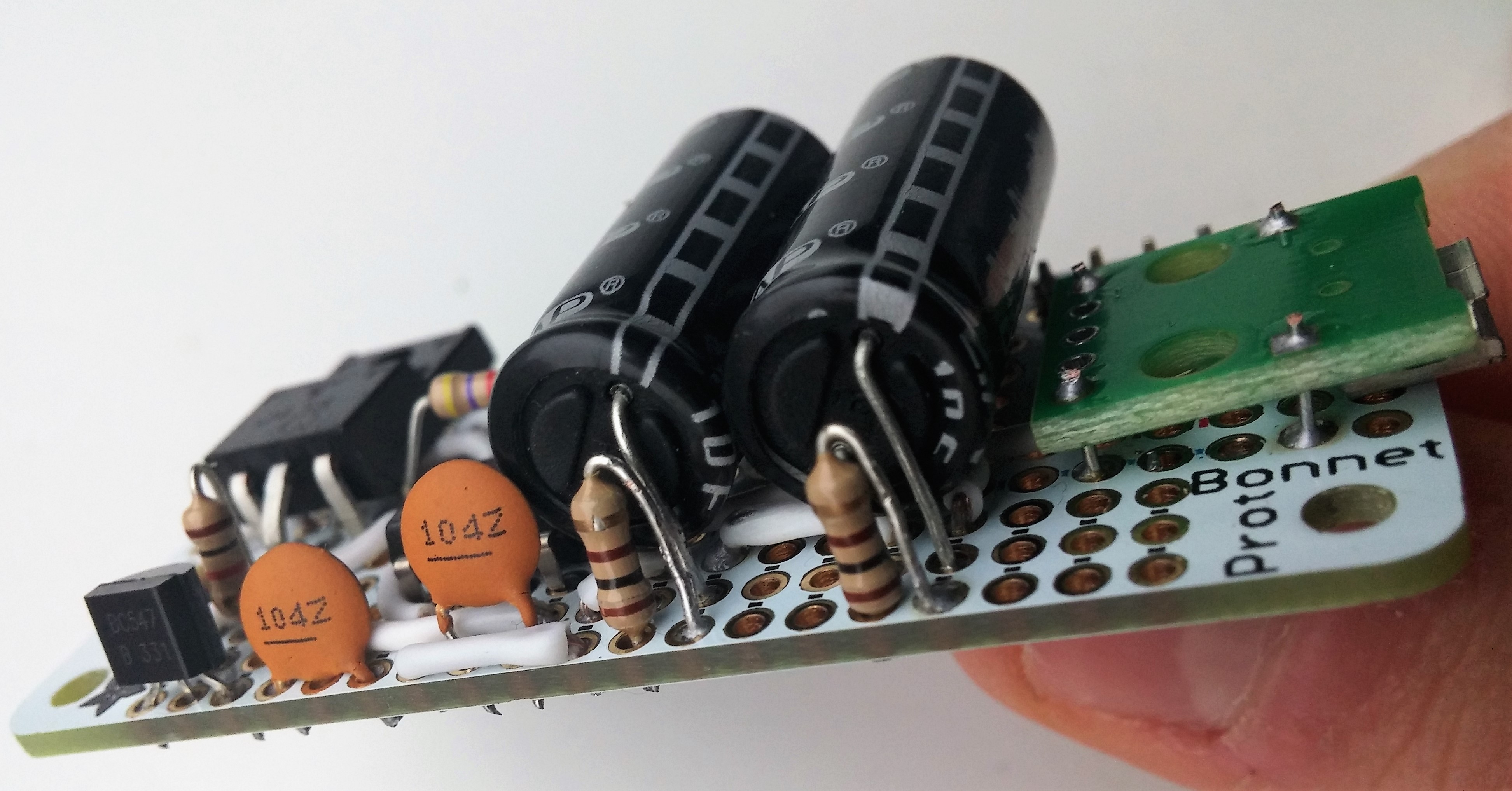
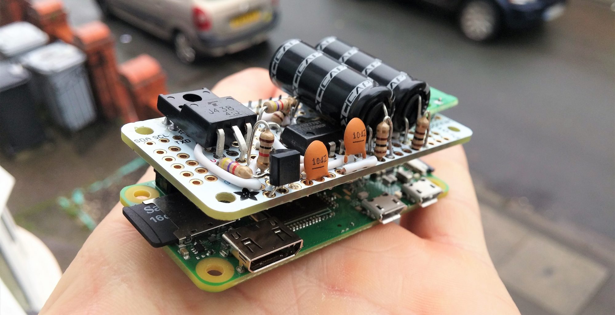
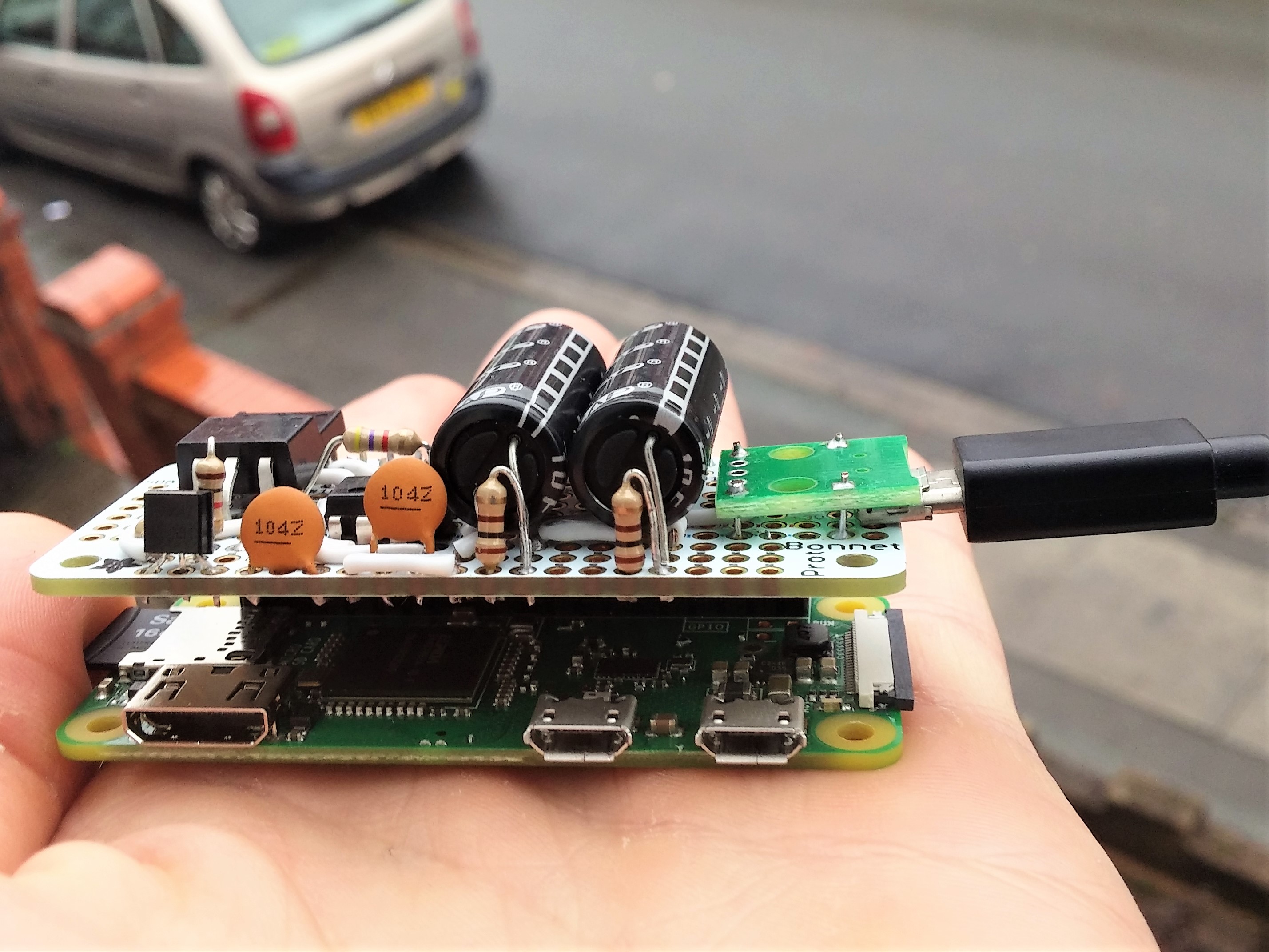
The final result looks like this:
STEP 7: Shutdown script
The last thing we need to do is write a script to shut down the Raspberry Pi when the voltage drops below 4.5V.
Turn on the Raspberry Pi and open the Terminal. Create a new file shutdownscript.py with this command:
sudo nano /home/pi/Desktop/shutdownscript.py
And fill it with this content:
#!/usr/bin/python
# Import required libraries
import RPi.GPIO as gpio
import os

# set the numbering system
gpio.setmode(gpio.BCM)

# set GPIO18 as input
gpio.setup(18, gpio.IN)

# wait for a rising edge
gpio.wait_for_edge(18, gpio.RISING)

# shut down the raspberry pi and hold
os.system('shutdown now -h')
Add this script to autostart of the Raspberry Pi. Therefore open the file ~/.config/lxsession/LXDE-pi/autostart with this command:
sudo nano ~/.config/lxsession/LXDE-pi/autostart
And add this line at the end of the file:
@/usr/bin/python /home/pi/Desktop/shutdownscript.py
Now, this script is started after every startup and shuts down the Raspberry Pi when a positive edge is detected at GPIO18.
Thanks to Andreas Spiess and his video, which inspired me to build this project. I modified his solution for my purposes.



12 Comments
Hossein · 22/10/2019 at 12:29
Hi
Thank you for you’r great project. I have made it and it works just fine, but some problems show up when I use lm 2896S ADJ Regulator madule with a diode ( 1n5408) in positive line after regulator and before supercapacitors. When I turn on the power lm2596s explodes. Also I use 12v switching power for powering lm2596s.
Any help would be greatly appreciated.
Techniccontroller · 22/10/2019 at 17:57
Hi Hossein,
thank you for your comment. As you see in the plots from the simulation the current at the beginning can be quite large. In the simulation, I put a resistor after the power supply in series to limit the current. I would recommend putting a small resistor (1-2 Ohm) after the lm2596s. I don’t know if this is the best solution, but it will save your lm2596s.
Regards Techniccontroller