I have the situation that I use a Raspberry Pi without a screen and other peripheries attached. It should work as Wi-Fi hotspot with a small web server on. To prevent the emergence of a corrupt SD card, I was looking for a solution to safely shutdown the Raspberry Pi simply by disconnecting the power supply.
In the following tutorial, I will show you how to build a small UPS (uninterruptible power supply) for your Raspberry Pi Zero for less than 10 Euro. The UPS will automatically trigger a safe shutdown when the power supply is disconnected.
STEP 1: Items you will need
You need the following components for the MiniUPS:
1x Adafruit Perma Proto Bonnet Mini Kit | 6,00 € |
2x Super Capacitor 10F 2.7V | 1,40 € |
1x TL7705BCP Supply-Voltage Supervisor | 1,00 € |
1x Micro USB To DIP Adapter | 0,25 € |
1x BC547 NPN Bipolar Transistor | 0,20 € |
1x 2SJ438 P-Channel MOSFET Transistor | 0,50 € |
2x Ceramic 0.1uF Capacitor | 0,20 € |
Resistors (2x 10k, 2x 4k7, 1x 1k, 2x 100) | ~0,10 € |
some wires | |
| Total | 9,60 Euro |
Additional you need the following tools:
- Soldering Iron
- Solder
- Electric pliers
- Cutter knife
STEP 2: Explaining the circuit
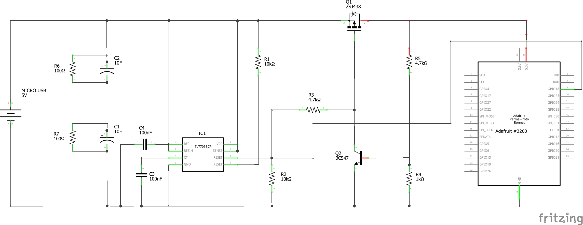
Picture 1: complete circuit of the MiniUPS
I use supercapacitors to buffer the voltage until the Raspberry Pi shuts down. The safe shutdown is triggered by a TL7705BCP supply-voltage supervisor, which turns its RESET output HIGH at a voltage below 4.5V. A small script runs on the Raspberry Pi in the background to start the shutdown on a rising edge on a GPIO pin.
Since charging the supercapacitors takes a few seconds and leads to a slowly rising voltage, some USB devices have problems on startup. We, therefore, insert an automatic switch, which we use to supply the Raspberry Pi with voltage only when the voltage has reached a value of 4.5V. Here again, we use the RESET output of the voltage supervisor to switch on the MOSFET transistor only from a voltage of 4.5V.
However, so that the MOSFET does not block directly at low voltage, we implement latching of the MOSFET with the bipolar transistor BC547B. Only when the voltage has fallen below a value of about 3.4 V, the MOSFET disconnects the supply voltage of the Raspberry Pi.
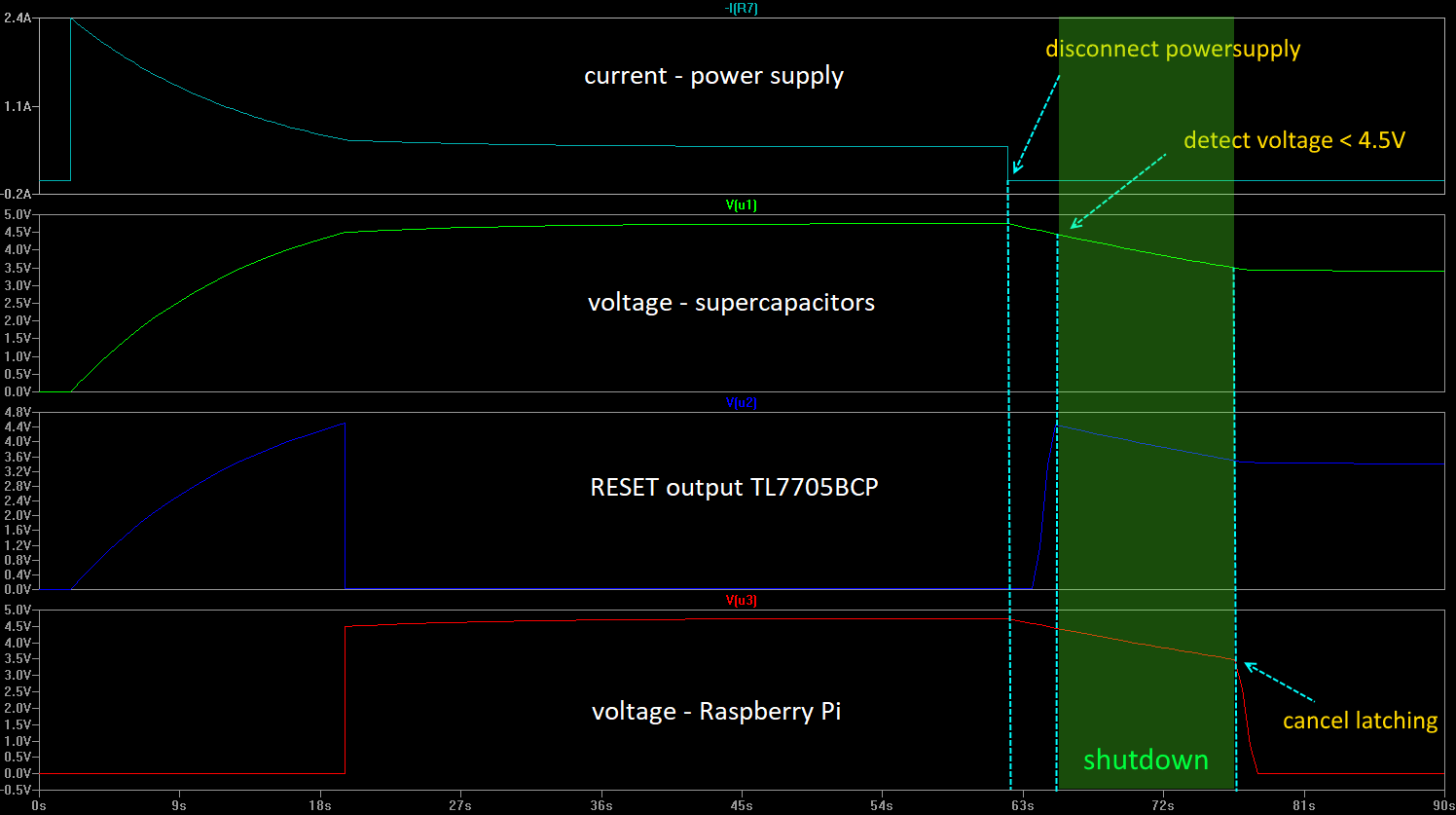
This time between 4.5V and 3.4V is usually enough to shut down the Raspberry Pi. Only if large consumers (e.g. a monitor) are powered via USB from the Raspberry Pi it could be scarce, here it could help to increase the supercapacitors to 20F.
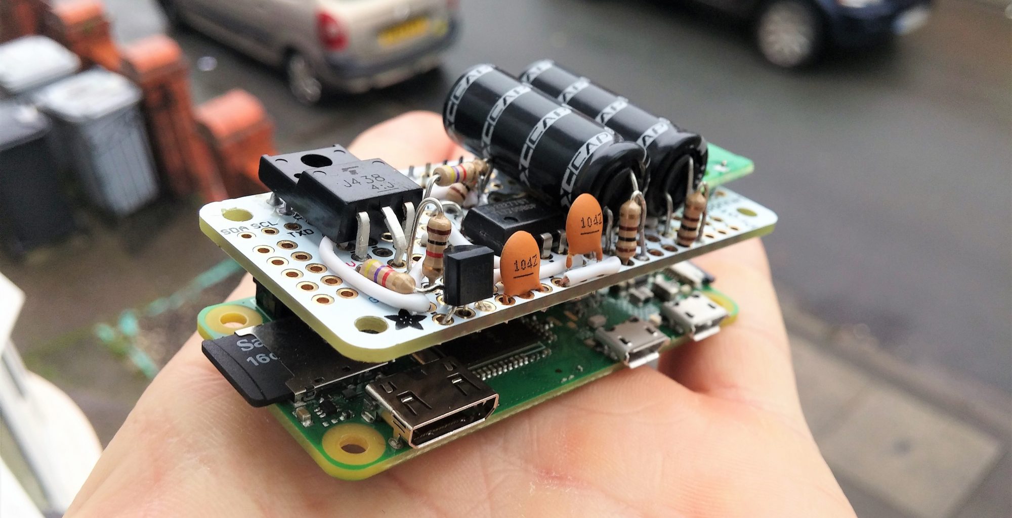
To simplify handling, I build the circuit on a prototype board from Adafruit and add a micro USB to DIP adapter.
I have the circuit in advance with LTSpice simulated. Here you can download my model of the circuit: MiniUPS_Simulation_LTSpice.asc
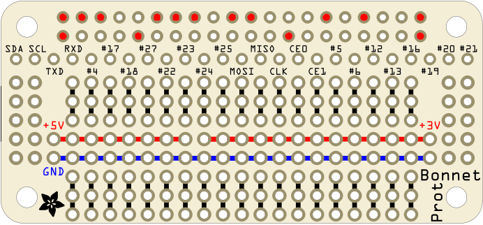
STEP 3: Prepare the prototype board
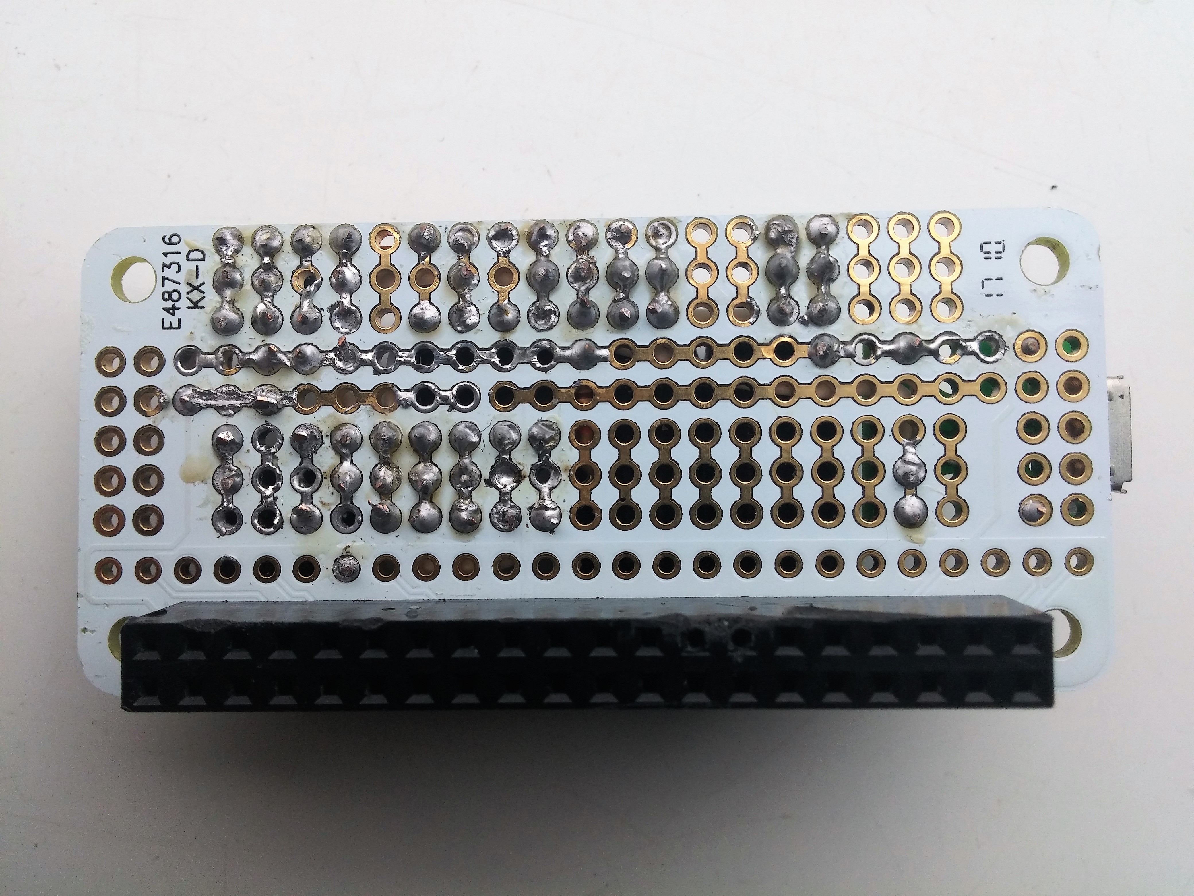
First, we need to solder the header to the prototype board, but we only need a few pins, so I’ve just soldered these to the board:
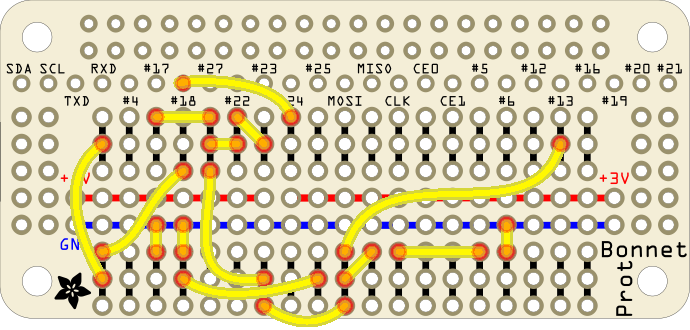
STEP 4: Wires
Solder the wires as shown in the picture below
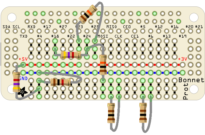
STEP 5: Resistors
Place the resistors as shown in the picture below:
STEP 6: Other Parts
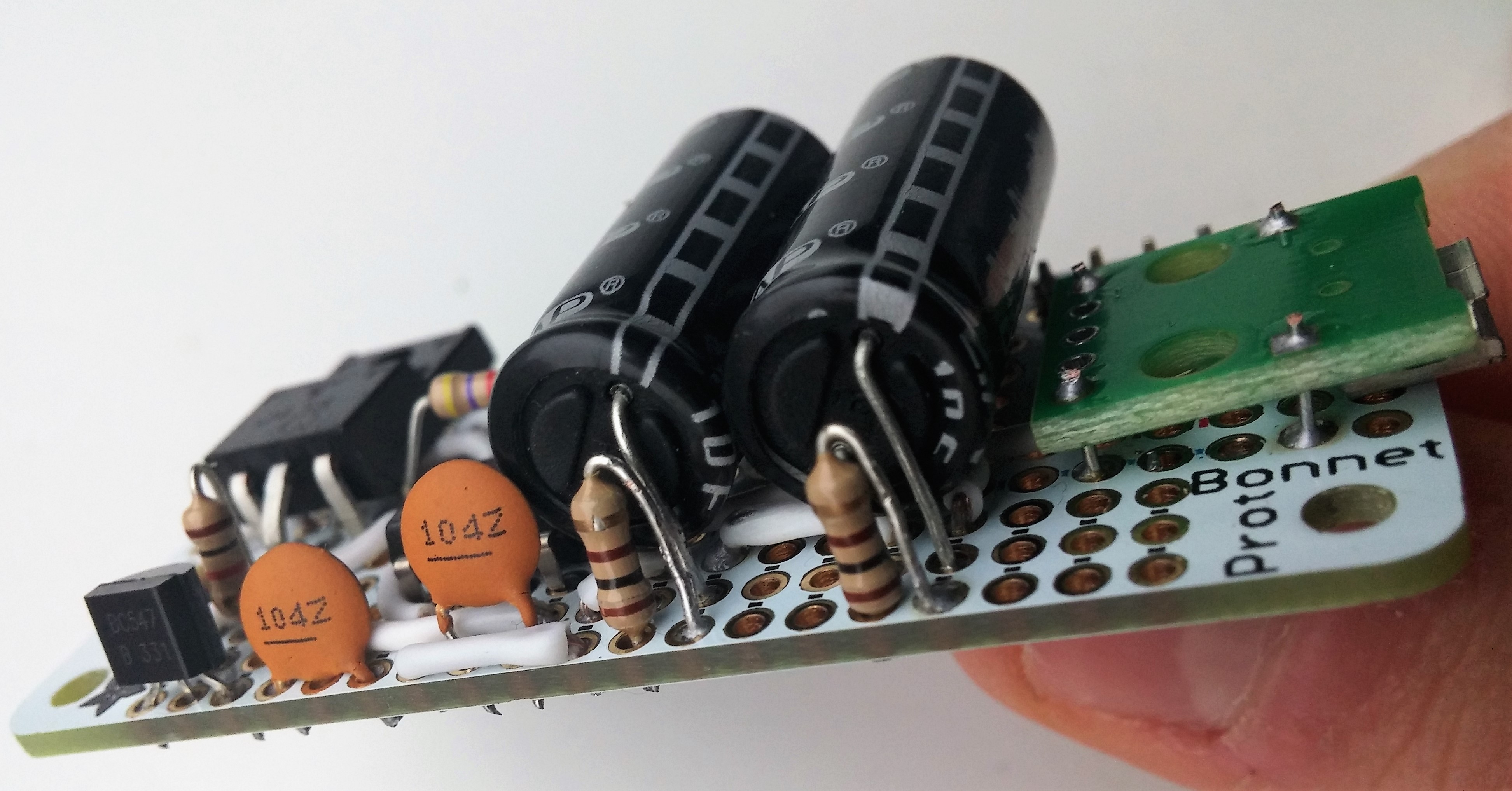
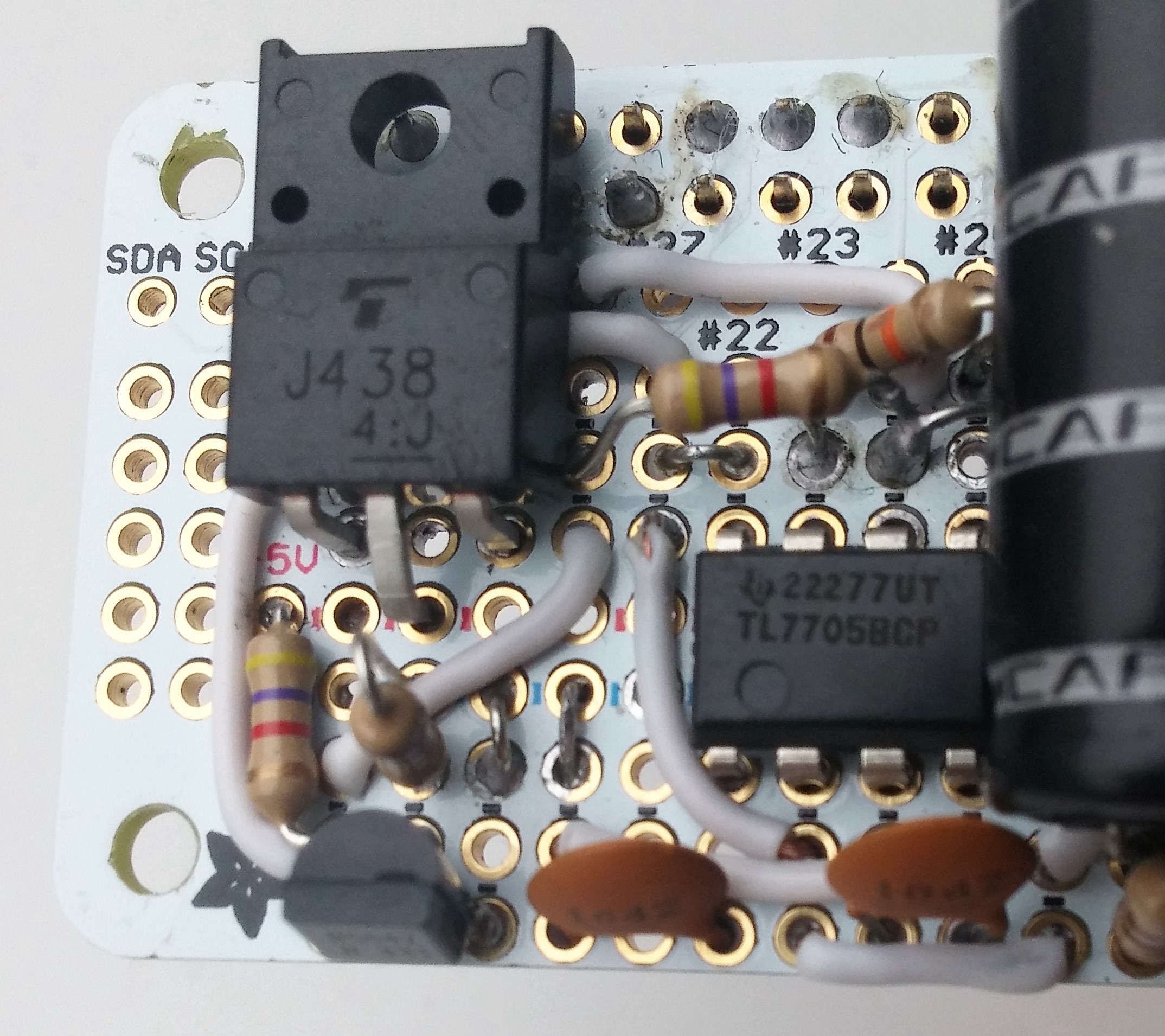
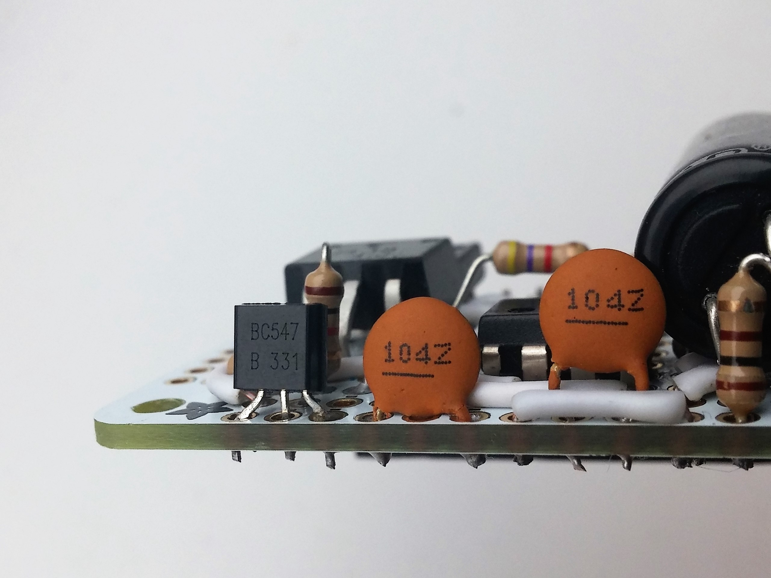
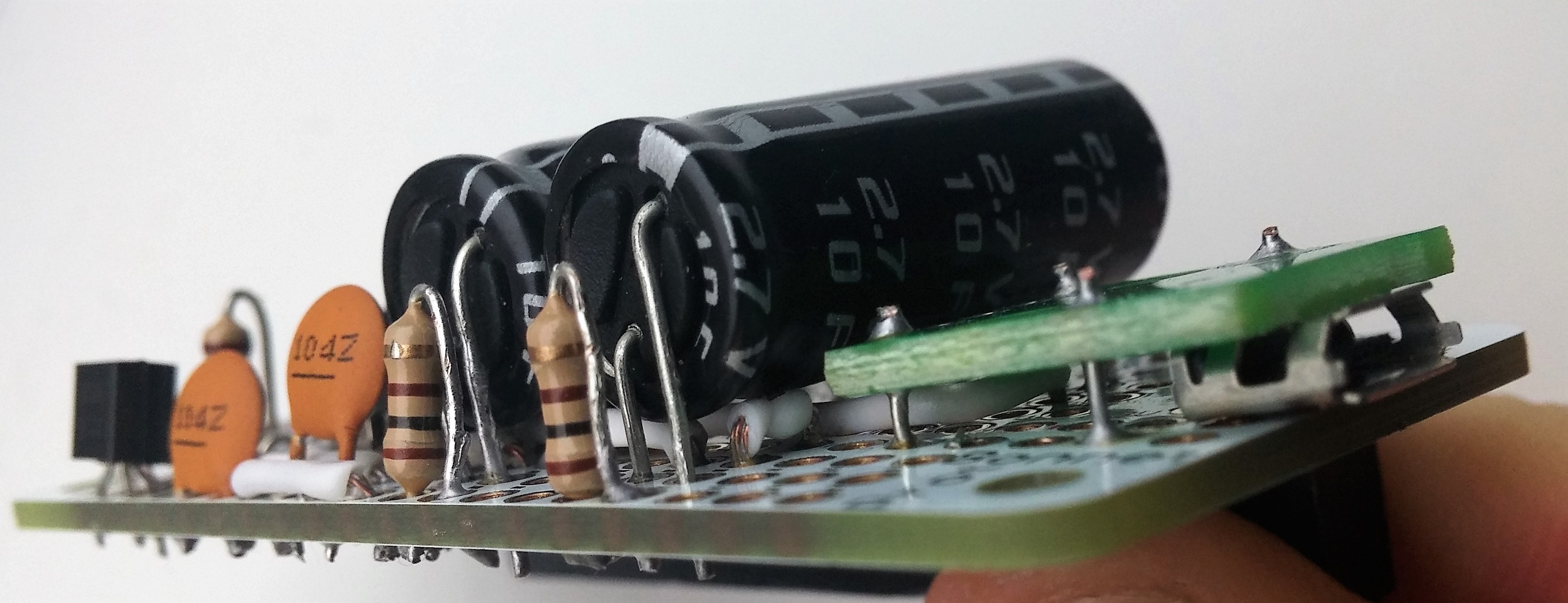
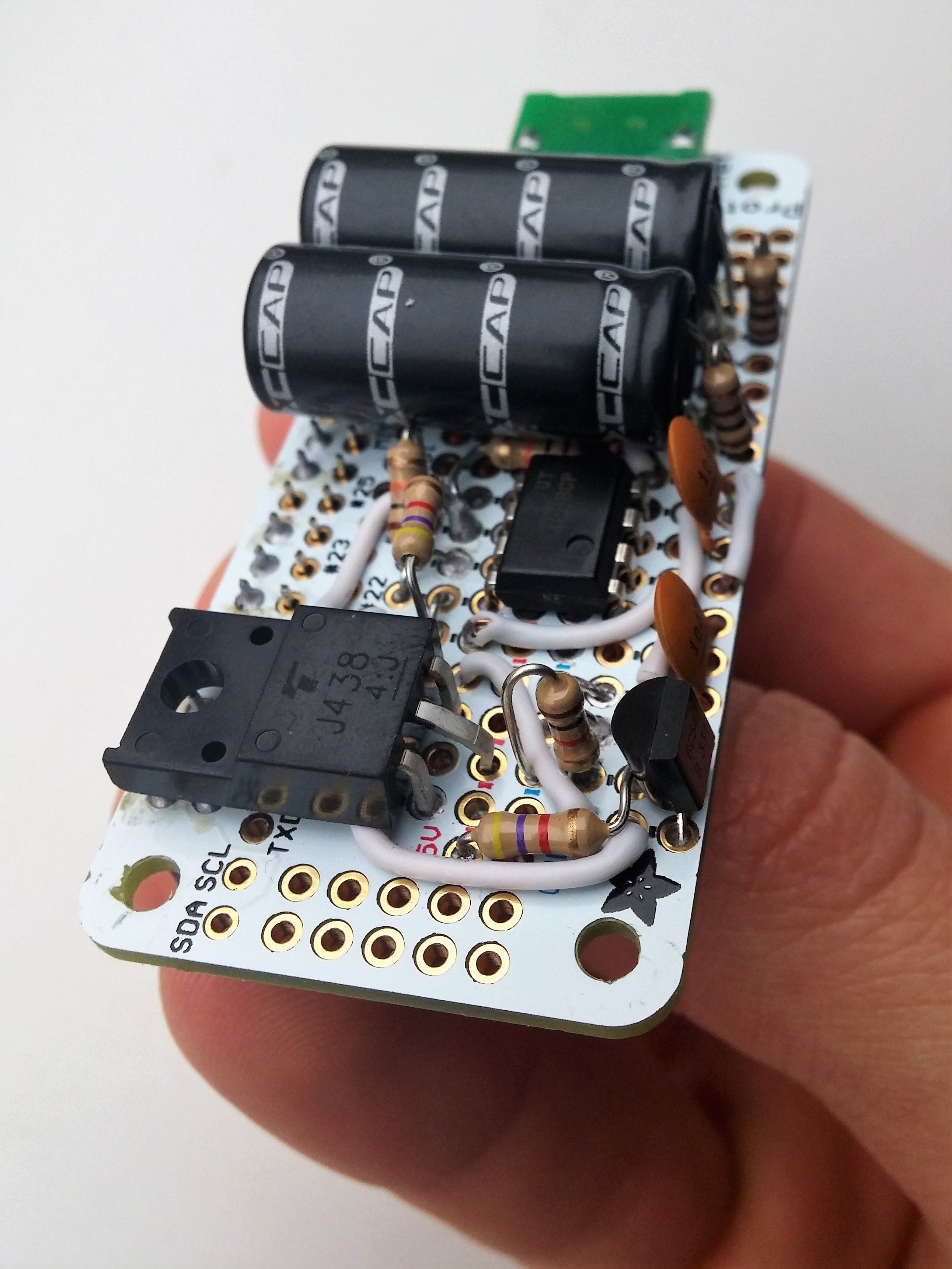
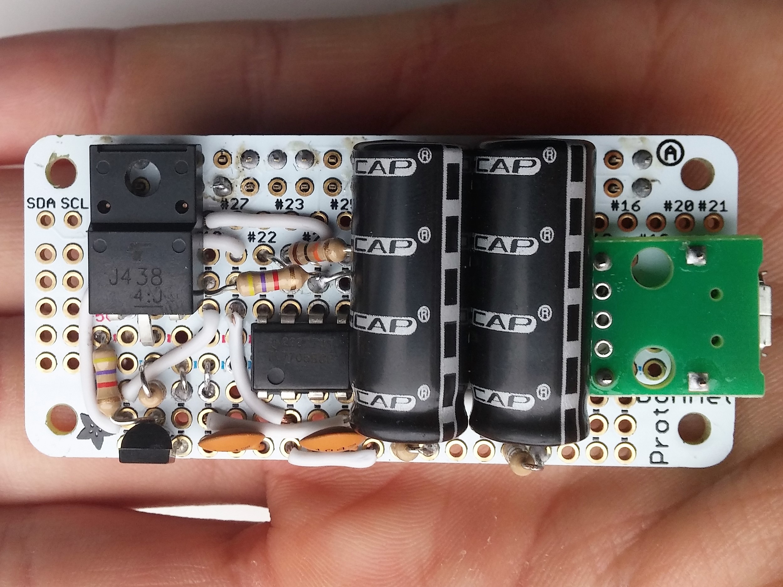
Now you can add the larger parts:
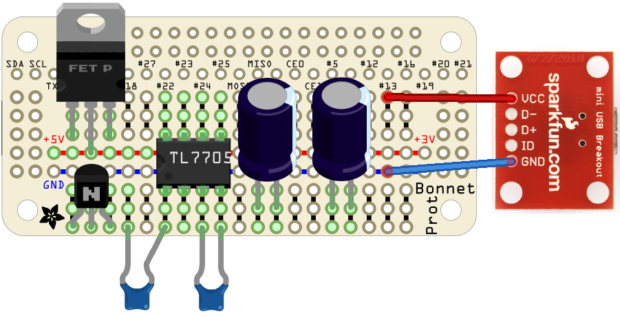
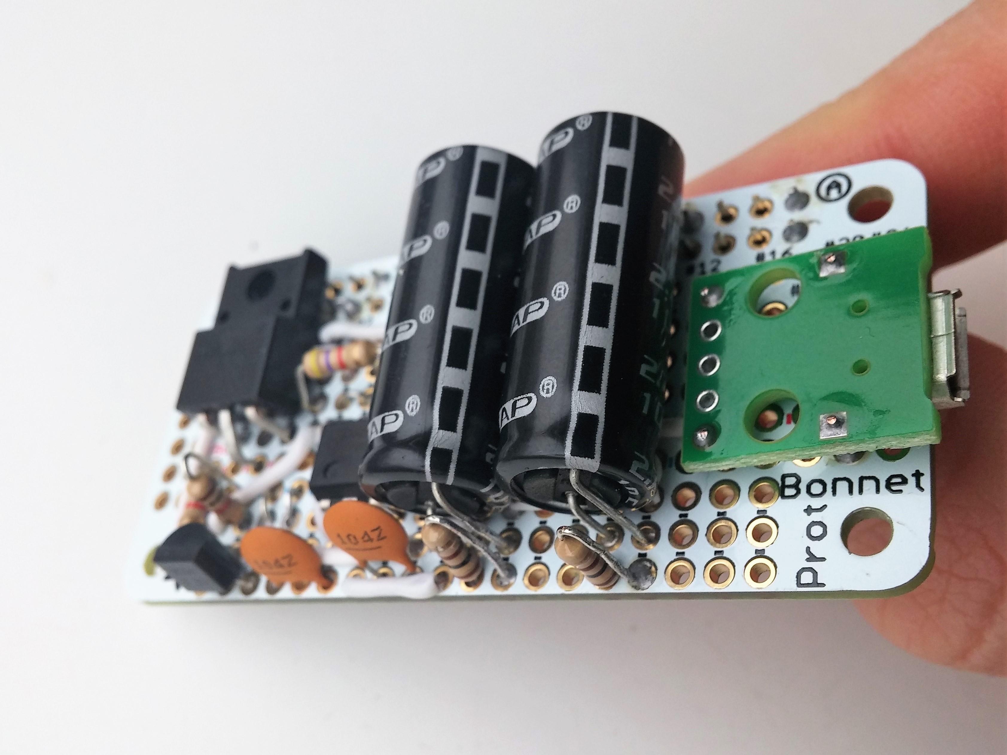
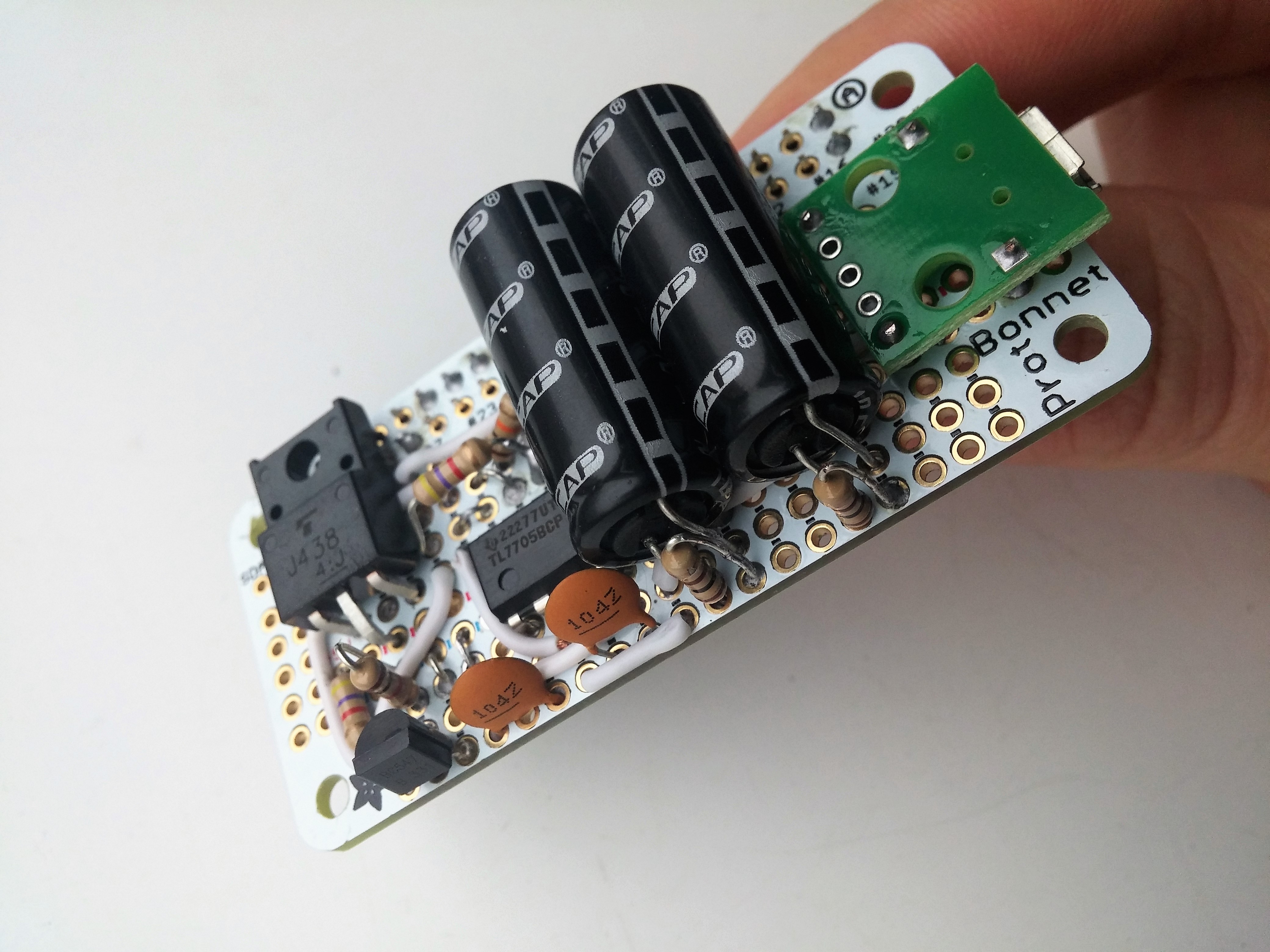
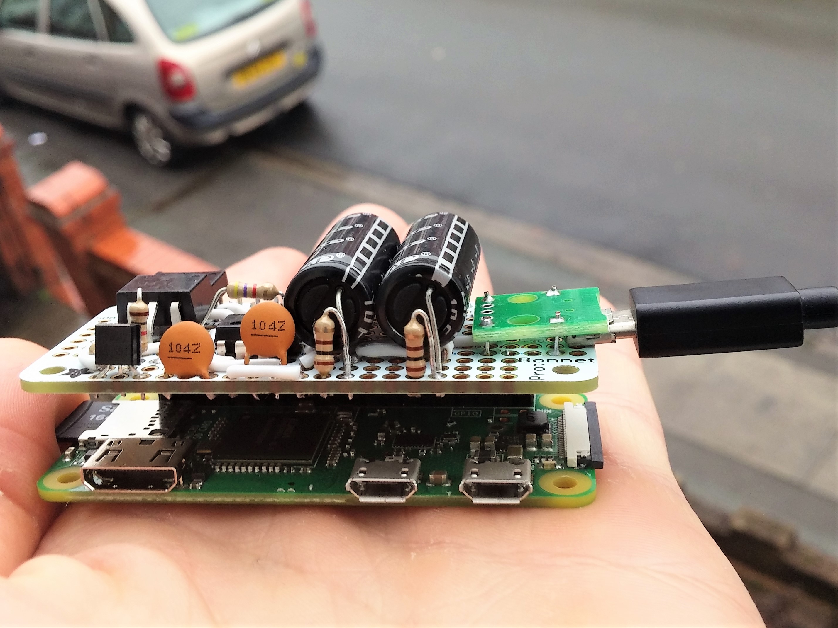
The final result looks like this:

STEP 7: Shutdown script
The last thing we need to do is write a script to shut down the Raspberry Pi when the voltage drops below 4.5V.
Turn on the Raspberry Pi and open the Terminal. Create a new file shutdownscript.py with this command:
sudo nano /home/pi/Desktop/shutdownscript.py
And fill it with this content:
#!/usr/bin/python
# Import required libraries
import RPi.GPIO as gpio
import os

# set the numbering system
gpio.setmode(gpio.BCM)

# set GPIO18 as input
gpio.setup(18, gpio.IN)

# wait for a rising edge
gpio.wait_for_edge(18, gpio.RISING)

# shut down the raspberry pi and hold
os.system('shutdown now -h')
Add this script to autostart of the Raspberry Pi. Therefore open the file ~/.config/lxsession/LXDE-pi/autostart with this command:
sudo nano ~/.config/lxsession/LXDE-pi/autostart
And add this line at the end of the file:
@/usr/bin/python /home/pi/Desktop/shutdownscript.py
Now, this script is started after every startup and shuts down the Raspberry Pi when a positive edge is detected at GPIO18.
Thanks to Andreas Spiess and his video, which inspired me to build this project. I modified his solution for my purposes.


12 Comments
Joyce Ray · 01/07/2019 at 17:45
Hi,
I am getting stuck at this command – /home/pi/.config/lxsession/LXDE-pi/autostart, using a Pi Zero and Raspbian Jessie Lite. The terminal says No such File or Directory. Please help if you can.
Thanks.
Techniccontroller · 20/07/2019 at 11:17
the path may defer between the different Raspbian versions, but should be similar. Can be /home/pi/.config/lxsession/LXDE/autostart
Felix · 12/03/2019 at 20:17
Hi Techniccontroller,
the Mini UPS ist exacly what I need for my project. Thanks a lot for sharing it! I’m just an electronic amateur and tried to figure out what I have to change, if I don’t want to drain more than 0,9A from the power supply (USB 3.0 in my case). Therefore I downloaded the LTSpice model and installed LTSpice. Everything I tried to change so far didn’t worked out. Do you have any suggestions how to achieve my objective? Thanks in advance.
Cheers, Felix
P.S.: Sorry for my bad english – it’s not my mother tongue.
Techniccontroller · 12/03/2019 at 21:16
Hi, Felix,
Thank you very much for your comment. I just did a little test on the LTspice model and found out that you can limit the current at the input to about 1A by increasing the left resistor (R7) to 5 Ohm. But this leads to a longer charging time (~70 sec.), so you have to set the frequency of the voltage source to (100s /200s) and also increase the simulation time (stop time is now 200s).
But then a second problem occurs: The simulated raspberry pi consumes a lot of current, so it generates a voltage divider with the increased resistor, resulting in a low voltage at the output. A solution to improve the simulation is to increase the resistance on the far right to maybe 20 or 30 ohms.
I’m not a professional, but I think you can test your application with an additional resistor (~5 Ohm) in serial to the input and check if your USB device is still working properly.
This is my very simple solution. If you have found another solution, I would be happy to hear from you.
Cheers Techniccontroller
Chuck · 16/02/2019 at 5:39
Hi Techniccontroller,
All worked well 🙂 I’ve created your circuit and added “active supercap charge leveling” thanks to an additional video / circuit by the guru Andreas Spiess. The suggested amendment is here….. http://www.sensorsiot.org/simple-and-cheap-way-to-protect-your-super-caps-video-139/ It shows an “active supercap leveling circuit” by Andreas as he noted an error in his video. Andreas circuit uses additional components: 2, TL431 and 6 resistors to create balanced charging of the Supercaps.
It all worked well both circuits combined. But I have a situation.. If the power is turned off momentarily then turned on say 7 or so seconds later, the RasPi fails to boot. Power goes to the SuperCap to charge and gradual increasing power is then feed to the RasPi and hence it does not boot up. I then disconnect the circuit and reconnect to boot. So I added a boost converter between the RasPi and the circuit (which should provide 300ma) , but it didn’t work. I think the RasPi requires more amps on startup, alternatively maybe adding the boost converter before Q1 and Q2 maybe a solution? Any comments welcomed. Great site, thanks for sharing your knowledge. Regards Chuck, from Australia
Techniccontroller · 17/02/2019 at 11:16
Hi Chuck,
Thank you very much for your detailed comments and additional notes on “active supercap leveling circuit”. It was my first project with supercaps and I will take it into account for my next project 🙂
I have observed your described behavior on my RasPi, too. I think it’s due to the RasPi, which only boots after it gets 0V Voltage for a short time. Since it doesn’t consume any power after switching off, the supercaps only discharge very slowly and don’t reach 0V in 7 seconds (In fact, I never measured time it takes to reach 0V – maybe a few minutes?). But I didn’t find a solution for this problem and didn’t look for it explicitly, because I don’t disconnect and connect my Raspberry Pi so fast.
Let me know when you have found a solution.
Regards Techniccontroller
Toby · 28/12/2018 at 15:41
Hi,
awesome post, would love to build your UPS but have issues finding 2SJ438 and TL7705BCP in local stores.
I think I can replace the power supervisor with a TC 1232 CPA, but I don’t seem to find a good substitute for the FET.
Could you name another FET that I could use, ideally one which I can get at segor or, if necessary, conrad?
Initially I thought to use a IRF9530 but I’m not sure it’ll handle the voltage drop to 3,4v very well when shutting down..
Thanks a lot!
Techniccontroller · 28/12/2018 at 17:44
I built this project with components I bought on eBay. So it is possible that some parts not available anymore.
As a replacement of the MOSFET, you can try to use any P-channel MOSFET with a low Gate-Threshold Voltage (< 2V). In the datasheet of the MOSFET you need to look for the Gate-Source Voltage diagram, if the drain current at about 3V (Gate-Source Voltage) is already high enough to power the Raspberry Pi, it should be fine.
After a short search, this MOSFET might fit: NDP6020P
Yangmin Shen · 20/12/2018 at 2:09
Thanks for the great write-up. I plan to build a few of these, but I noticed that the 2SJ438 mosfet is discontinued and becomi g hard to source.
Can you recommend an eqivalent part or alternative circuit?
Thanks for your help.
Techniccontroller · 28/12/2018 at 17:52
Sorry for my late reply.
You can use any P-channel MOSFET with a low Gate-Threshold Voltage (< 2V). In the datasheet of the MOSFET you need to look for the Gate-Source Voltage diagram, if the drain current at about 3V (Gate-Source Voltage) is already high enough to power the Raspberry Pi, it should be fine.
One possible MOSFET could be the NDP6020P.