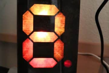
After my Wordclock 2.0 and Ringclock, I want to present my third clock, which has an ESP8266 and Neopixel-LED. I call it DigitalClock because I use NeoPixel-LEDs to display four seven-segment displays. LEDs also illuminate the dynamically changing background.


Features of the clock:
- receives time updates via a NTP server
- automatic switches between summer and winter time
- provides easy WIFI setup with WifiManager
- has an HTML webserver interface for configuration and control
- color of the display is configurable
- night mode is configurable (start and end time)
- the brightness of LEDs is adjustable
- an automatic current limiting of LEDs protects the power supply
Content
- Material for the DigitalClock
- Building the Hardware
- 1. STEP: Wooden Frame
- 2. STEP: Light Guiding Grid
- 3. STEP: LED Strips
- 4. STEP: Electronic Components
- 5. STEP: Frontplate
- 6. STEP: Final Assembly of the DigitalClock
- The Software
1. Material for the DigitalClock with NeoPixel and ESP8266
You need the following material for building this clock:
- Wooden board, 300×300 mm, 18 mm thick
- Plywood board, diameter 260 mm, 3 mm think
- NeoPixel-Strip with 33x WS2812b LEDs (60 LEDs/m) (amazon.de*),
- NeoPixel-Strip with 46x WS2812b LEDs (30 LEDs/m) (amazon.de*),
- D1 Mini ESP8266 (amazon.de*),
- USB power supply 5V/3A (amazon.de*),
- Acrylic glass panel (color: frost opal white, thickness: 3mm, diameter 220 mm) (kunstoffplattenonline.de),
- 470 Ohm resistor,
- 1000uF capacitor,
- USB-C breakout socket (ebay.de),
- micro USB breakout plug (ebay.de),
- USB-C cable (amazon.de*)
- 4x small screws
- some small nails
- some cables
- some transparent and black spray paint
Additionally, some special tools are needed:
- soldering iron
- hot glue
- cutter knife
- 3D-Printer (see FAQ if you have no 3D printer)
* The links are affiliate links. The offers do not come from me, however, I receive a commission through the reference, if then a purchase takes place, but without you incurring additional costs.
2. Hardware
STEP 1: Wooden Frame
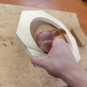
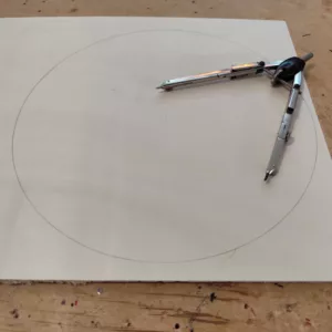
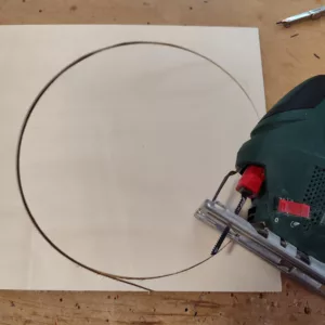
The clock features a frame made from 18mm thick spruce wood, which needs to be cut to size first. I started by cutting the board to a square shape of 300×300 mm. Next, I marked the inner circle with a diameter of 220 mm and an evenly spaced octagonal pattern with a side length of approximately 124 mm. Using a jigsaw, cutting the board to its final shape was straightforward. I used sandpaper for a clean finish to smooth out rough edges. Some transparent spray paint gives a nice, shiny look.


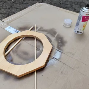
Similarly, the back panel can be cut from 3mm plywood. I opted to paint it black to reduce reflections. However, in future builds, I would recommend painting it a lighter color, as I did with my word clock, to create more even indirect lighting.

STEP 2: Light Guide Grid
To properly display the four seven-segment digits with LEDs, a corresponding grid structure is required. This grid includes the digit segments and two dots. A 3D printer is ideal for creating this structure. I printed the grid using black PLA to minimize light bleeding between segments. The STL file for the grid is available for download here:

(Turn the 3D object with your mouse/finger)
STEP 3: LED Strips
I used two different types of LED strips to avoid excessive cutting and soldering. The grid was designed to match the LED pitch of these strips: 30 LEDs/m and 60 LEDs/m.
The accompanying images show how I cut the LED strips and attached them to the back panel using their built-in double-sided adhesive. Arranging the LED strips in a zig-zag pattern is crucial to simplify wiring. The LED strip color is not relevant; I used different colors only to illustrate the difference better. The white strip has 30 LEDs per meter, while the black strip has 60 LEDs per meter.
To ensure even illumination of the background, I cut and redistributed the middle black LED strips. Once all LED strips were in place, I soldered them in series using short wires.


STEP 4: Electronic Components
The electronic components are pretty simple. The wiring is similar to my RingClock project, but only one LED strip is controlled here instead of two. The wiring diagram is provided below.

To properly integrate the USB-C connector and ESP8266 within the frame, I had to modify the wooden frame slightly:
- I carved a small pocket in the frame for the ESP8266. This can be done with a chisel or a sharp knife.
- For the USB-C port, I drilled a 15mm-wide slot on the bottom side of the frame. I started by marking the slot, then drilling multiple small holes, gradually increasing the drill size. Finally, I refined the slot using a file to ensure a proper fit.
- The USB-C module was then secured with hot glue.


STEP 5: Front Plate
Before final assembly, the front plate needs to be glued into the wooden frame. To strengthen the bond, I used small nails as additional support:
- I marked the 3mm thickness of the front plate on the frame.
- Then, I hammered small nails around the perimeter at regular intervals, leaving 2-3 mm protruding.
- I lightly sanded the contact surfaces to improve adhesion between the hot glue and the acrylic front plate.
- The front plate was glued into place using hot glue, with the nail heads providing extra grip.


STEP 6: Final Assembly of the DigitalClock
To complete the assembly:
- Attach the grid to the back panel using hot glue. Some areas may not sit flush due to solder joints or wiring—trim small sections of the PLA with a knife as needed.
- Secure loose electrical components with a few dabs of hot glue.
- Attach the back panel to the frame using four small wood screws.
- To make wall mounting easier, I 3D-printed a small hook (STL file), which I attached to a recessed hole on the back of the frame using screws.


With the final assembly complete, the digital clock is ready to be powered up and tested! Now, let’s move on to the software setup, where we’ll configure the ESP8266 to control the LEDs and bring the clock to life.
3. Software
Quickstart
For those who want to get started directly with the code, you can find the complete source code on GitHub:
techniccontroller / digitalclock_esp8266
ESP8266 source code for DigitalClock on GitHub
- Just clone the project into the sketch folder of the Arduino IDE,
- Install the additional libraries and flash it to the ESP8266 as usual.
- The implemented WiFiManager helps you to set up a WiFi connection with your home WiFi -> on the first startup it will create a WiFi access point named “digitalclockAP”. Connect your phone to this access point and follow the steps shown to you.
- After a successful WiFi setup, open the browser and enter the IP address of your ESP8266 to access the interface of the web server.
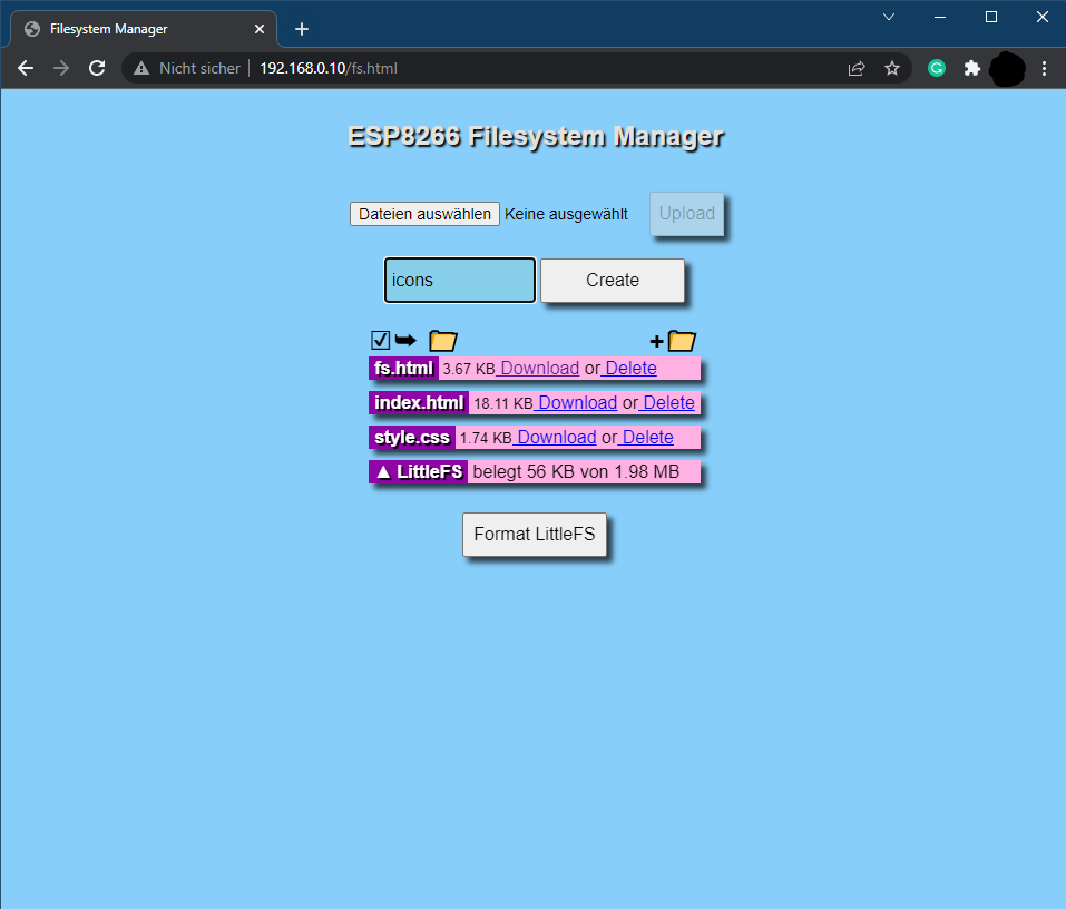
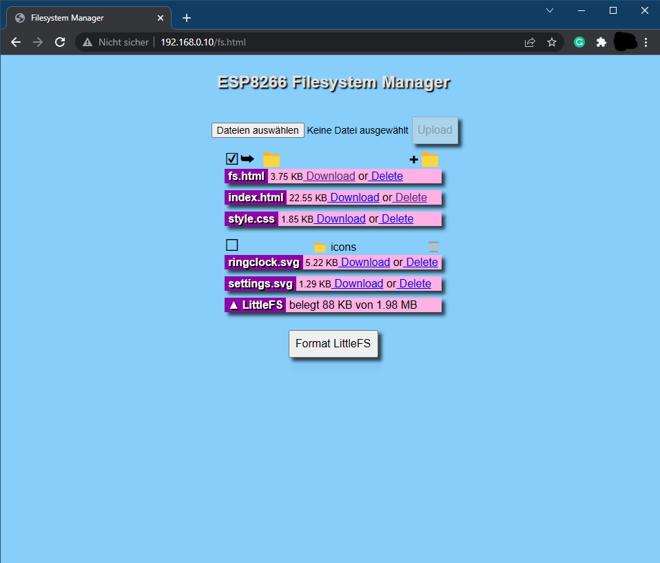
- Here, you can upload all files, that are located in the folder “data”. Please make sure all icons stay in the folder “icons”.
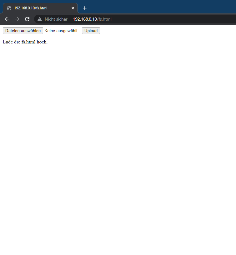
- Open http://<ip-address>/fs.html in a browser
- Upload fs.html
- Upload style.css
- Upload index.html
- Create a new folder icons
- Upload all icons into this new folder icons
The DigitalClock is now ready. Navigate to http://<ipaddress>/ or http://digitalclock.local/ to open the web server interface of the DigitalClock and have fun with it!


Detailed Look
For anyone interested in delving deeper into the software’s internals, I’d like to offer a more detailed explanation here. Those familiar with my Word Clock 2.0 or RingClock article might recognize a significant overlap between the source codes of these projects. I’ve repurposed substantial portions of the Word Clock 2.0 code for the DigitalClock software, maintaining a consistent software architecture. The diagram below outlines the software’s structure, highlighting both third-party and my own libraries. Additionally, to streamline the code, I’ve outsourced certain functionalities into distinct .ino files.

Please see the article on my RingClock for small descriptions of NTPClientPlus, UDPLogger, otafunctions.ino and LittleFS.ino modules.
I added two new own libraries and one more functionality file:
LEDStrip
Similar to the library LEDRings in my RingClock or LEDMatrix in Wordclock 2.0, it encompasses all functions necessary for controlling the LEDs of DigitalClock, including those for initialization, individual pixel manipulation, brightness adjustment, and current limiting.
SegmentClock
The SegmentClock library integrates with an LEDStrip to illuminate the digits of the DigitalClock. It features methods to set the time, adjust brightness, and even randomize the background colors for a visually striking effect. Each digit is mapped to a specific set of LEDs, ensuring encapsulated control over every segment.
timezonefunctions.ino
As some users of my Wordclock 2.0 project requested, I’ve added a simple way to set the clock’s timezone automatically. This file includes functionality to detect the current timezone based on the device’s IP address using the lightweight API provided by ip-api.com.
The API returns detailed location data based on your public IP, including the timezone and offset. This makes it easy to automatically adjust the clock without needing manual configuration.
You can test the API by entering the following URL in your browser:
http://ip-api.com/json/?fields=status,message,country,countryCode,region,regionName,city,zip,lat,lon,timezone,offset,query From the JSON response, the timezone offset can be extracted and passed to the NTPClientPlus object to set the correct local time.
Have fun rebuilding it! If you have any questions, please feel free to write a comment.


4 Comments
roberto · 10/10/2025 at 10:59
You’re great!…It’s just that you’re making my house fill with clocks. 😂
Kai · 01/04/2025 at 17:25
Moin Edgar,
klasse Projekt, wie das letzte. Mit der Lib AdafruitNeoPixel 1.12.5 hat das Kompilieren nicht funktioniert, habe dann 1.12.4 genommen.
Alles zusammen in einen Bilderrahmen. Sieht Mega aus, Danke für die tollen Projekte !!!!
Lieben Gruß
Kai
Techniccontroller · 06/04/2025 at 9:33
Hallo Kai,
vielen Dank für dein Kommentar.
Bei mir tritt der Compile-Fehler mit 1.12.5 nicht auf. Ich habe es grade nochmal ausprobiert. Wenn der Fehler bei dir noch auftritt, wäre es für mich interessant die genaue Fehlermeldung zu sehen.
Viele Grüße
Edgar
Kai · 07/04/2025 at 14:04
Sorry, war mein Fehler. Alles funktioniert wie Du beschrieben hast.
LG Kai